11
OPERATION
The fuel selector switch cover is specifically
designed not to slide to either side while a specific
fuel has been selected and the valve is in the “ON”
position. Only when the fuel valves are in the “OFF”
position can the cover slide side to side.
NOTE
The fuel selector is locked into place once a
“CLICK” sound is made. Only then can a fuel valve
be turned to the vertical position.
NOTE
Fuel Selector Switch
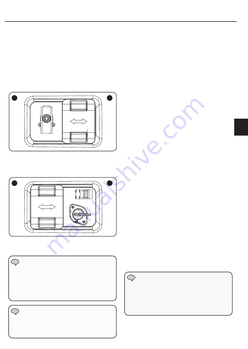
The fuel selector switch on the front panel of the
generator is designed specifically to choose between the
fuel source desired, Petrol or LPG.
To select a fuel source simply slide the switch cover to
either the right or left, and this will uncover the fuel
valve of the fuel selected.
The LPG fuel valve (A) is to the left of the switch cover.
The petrol fuel valve (B) is to the right of the switch cover.
1
A
2
B
Once a fuel source has been selected, the user must
turn the fuel valve to the vertical position to open the
fuel valve. (1)
To turn a fuel valve to the off position the valve must be
in the horizontal position. (2)
Starting the Engine in ambient > 15°C (59°F)
Petrol
1. Make certain the generator is on a flat, level surface.
2. Disconnect all electrical loads from the generator.
Never start or stop the generator with electrical
devices plugged in or turned on.
3. Turn the petrol fuel valve to the “ON” position.
4. Move the choke lever to the “100% CHOKE” detent
position.
a. For restarting a warm engine, move the choke
lever to the “75% CHOKE” detent position.
5. Push the battery switch to the “ON” position.
6. Push the ignition switch to the “ON” position.
7. ELECTRIC START: Press and hold the ignition switch
to the “START” position. Release as the engine begins
to start. If the engine fails to start within five seconds,
release the switch and wait at least ten seconds before
attempting to start the engine again.
8. RECOIL START: Pull the starter cord slowly until
resistance is felt and then pull rapidly.
9. Do not over-choke. As soon as engine starts, gradually
move the choke lever to the “RUN” position over a 2-5
second duration.
Dual Frequency Operation Guide
1. Turn the frequency switch to your selected option
before start the generator. (As Decal shows on the top
of the switch)
a. 60HZ: Turn the frequency switch to the Left until
the end point.
b. 50HZ: Turn the frequency switch to the right until
the end point.
2. Start the generator and check the intelligague meter
to ensure the frequency is correct. (You can press the
switch button until it shows frequency. )
3. Connect your device onto the generator.
Keep choke lever in “Choke” position for only 1
pull of the recoil starter. After first pull, move choke
lever to the “Run” position for up to the next 3
pulls of the recoil starter. Too much choke leads to
sparkplug fouling/engine flooding due to the lack of
incoming air. This will cause the engine not to start.
NOTE
EN
Summary of Contents for CPG5500E2DF-J
Page 2: ......
Page 21: ...19 Champion Generator 5500W JP...
Page 22: ...20...
Page 23: ...21 GFCI 91 4 cm 3 1 5 m 5 JP...
Page 24: ...22...
Page 25: ...23 OFF LPG LPG LPG PG OFF LPG LPG LPG LPG LPG 2 LPG LPG LPG LPG JP...
Page 26: ...24 1 2 3 1 2 3 4 R 5 2 1 2 1 2 3 1 2 1 2 2...
Page 28: ...26 10 30 1 2 3 4 5 6 4mm 6 4mm 6 85 6 4 mm...
Page 29: ...27 OPD LPG 12 AWG 2 052mm 3 309mm2 1 8kg 10kg LP LP LPG 1 2 LPG LPG LPG 3 4 LPG 5 LPG JP...
Page 30: ...28 1 5m 91 4cm 1 CSA UL1449 AC...
Page 34: ...32 1 2 3 1 2 1 1 2 3 4 5 6 7 5 6...
Page 35: ...33 1 2 3 4 5 6 7 1 2 3 4 0 7 0 8 mm 5 6 7 0 7 0 8 mm 0 028 0 031 in 1 15 mm 2 3 4 5 6 1 2 JP...
Page 36: ...34 25 PSI 1 2 3 4 5 6 25PSI 8 5 50 100 250 3 LPG...
Page 37: ...35 14 1 20 1 2 3 4 5 6 7 8 9 14 8mL 1 2 10 11 OFF 2 1 1 2 M5 10 M5 3 1 2 4 1 5 1 JP...
Page 38: ...36 OFF ON LPG AC AVR AVR https www youtube com watch v olRvvKBIyN0...
Page 46: ......
Page 47: ......
Page 48: ...814 0714 6 23 18...


