15
EXPLANATION OF TROUBLE SHOOTING GUIDE
1/2.
Check all fuses and switches on lines to motor to be sure it is receiving power. Check for loose or
faulty wires.
3.
A magnetic starter embodies a reset button which may be used to place the motor back in service
after some unusual power conditions.
4/5.
A pressure switch uses a diaphragm to open and close a set of points. Points may become pitted
or dirty through use. Clean by "touching up" with sandpaper or replace. See instructions in pressure
switch cover.
WARNING
Disconnect unit from power source before checking pressure switch.
6.
Low voltage is prime cause of motor trouble. Ask you power company to test for low voltage.
7.
Most electric motors are of the sealed bearing type. Check motor manufacturer's recommendation.
8.
Water in the form of vapor is compressed along with incoming air and condenses in tank. Tank must
be drained daily so that full storage capacity of tank may be used. To drain, relieve tank pressure,
open valve at bottom of horizontal or vertical tank. If compressor is equipped with automatic tank
drain, drain manually once a week.
WARNING
Do not open drain valve if tank pressure exceeds 25 PSIG.
9.
The fins on the cylinder and tubing should be free of dirt which acts as an insulation. This is easily
done by periodically blowing them clean or through the use of a wire brush.
9.
"V” belts must be tight enough to transmit the necessary power to the compressor. If too tight they
will overload the motor. If, by pushing down on one belt, its top lines up with the bottom of the belt
next to it, the tension is correct. Should it be necessary to change the tension, slide the engine or
motor in slots provided in tank baseplate to desired position.
WARNING
Disconnect unit from power source before checking or adjusting belts. Always reinstall belt guard
after adjusting belts.
11.
The fan blade flywheel must rotate in the direction shown by the arrows.
12.
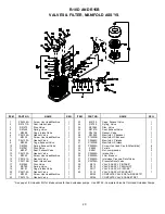
Compressor valves may become fouled by carbon or other foreign matter. To service, remove
manifold and extract valve. Remove screw in center of valve and clean all parts. Seat and disc may
be lapped in on fine sandpaper if badly carboned. If a smooth finish cannot be obtained, replace with
new parts. Reassemble and install, taking caution that all parts are returned to their original position
with screw head up.
13.
All air lines from compressor to tank and from tank to air operated devices should be tight. A soap
solution will show bubbles when put on a leaky joint. At 175 PSIG a 1/32" hole will allow almost 3
cubic feet per minute of air to escape.
14.
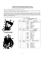
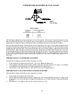
Pilot Valve adjustment is found on page 23.
15.
Check pilot valve for loose connections.
16.
The centrifugal unloader valve may become fouled by foreign matter. To clean, unscrew hex cap on
end of unloader, remove spring and ball, to remove ball, you may need to "rock" flywheel. Clean or
replace if necessary.
Summary of Contents for HR3-6
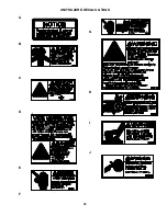
Page 25: ...25 UNIT HAZARD DECALS TAGS A B C D E F G H I J ...
Page 26: ...26 K L M N O P Q R S T U V W 140 175 PSIG ...
Page 27: ...27 PUMP HAZARD DECALS TAGS 1 2 3 4 5 6 ...
Page 31: ......


