23
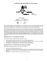
OPERATION AND ADJUSTMENT OF PILOT VALVES
PILOT VALVES
ASSEMBLY
PART NO.
PRESSURE RANGE,
PSIG
M2855
M2854
M2853
75 - 95
90-120
140 - 170
The Pilot Valve is designed to act as an automatic "on" and "off" air switch. When in the "on" position it allows air to flow
from the tank through the valve to some device such as a compressor suction unloader, thus actuating it. In the "off"
position this valve stops the flow of air through the valve and releases the pressure in the line to the device.
The Pilot Valve works as follows: Tank air pressure acts on the bottom of the valve. When pressure is great enough
to overcome spring force holding valve down on lower seat, it lifts off seat and allows air to flow around valve and out
through side opening in Pilot Valve. When valve lifts off lower seat it moves up and seats on upper seat where it is held
by tank pressure. When pressure in tank and on valve drops, spring forces valve back down on lower seat. Air in line
to device being actuated can then escape through upper seat and out vent hole. The pressure at which the Pilot Valve
is "on" or "off" is controlled by the spring which has been installed at the factory. A small adjustment can be made in
the field by changing the spring force by compressing the spring more or less with the adjusting screw provided on the
Pilot Valve.
COMPRESSOR PILOT VALVEPRESSURE ADJUSTMENT
Proceed with the following instructions while compressor is running:
1.
Loosen locknut (4) and back off several turns. Do not turn differential adjuster (3).
2.
Check reading on the tank pressure gauge. Set the compressor maximum pressure at 170 psig. Turn threaded
cap clockwise to increase pressure or counterclockwise to decrease pressure.
3.
After pressure is set, tighten locknut (4). Be careful not to move the threaded cap (1).
COMPRESSOR PILOT VALVE DIFFERENTIAL PRESSURE ADJUSTMENT
Proceed with the following instructions while compressor is running:
1.
Loosen locknut (2) and back off several turns.
2.
Check reading on the tank pressure gauge. Set the pressure to 30 psig differential (unload at 170 psig, reload
at 140 psig). Turn nut (3) clockwise to increase differential pressure or counter-clockwise to decrease differential
pressure.
3.
After pressure is set, tighten locknut (2). Be careful not to move nut (3).
B980-B
(Ref. Drawing)
Summary of Contents for HR3-6
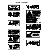
Page 25: ...25 UNIT HAZARD DECALS TAGS A B C D E F G H I J ...
Page 26: ...26 K L M N O P Q R S T U V W 140 175 PSIG ...
Page 27: ...27 PUMP HAZARD DECALS TAGS 1 2 3 4 5 6 ...
Page 31: ......


