13-11-614 Page 19
DANGER
Hot water under pressure will cause severe personal injury or death. Do not
operate compressor until a water drain line is installed from compressor water
drain port to a floor drain.
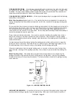
AIR/WATER RESERVOIR
- The air/water reservoir-separator combines multiple functions into one
vessel. The lower half functions as a reservoir, providing water storage capacity for the system and the
upper portion serves as primary air/water separation. The reservoir also provides limited air storage for
control and gauge actuation.
COMPRESSOR INJECTION WATER SYSTEM CHECK
- The following readings are based on an
ambient temperature of 80
°
F inlet cooling air on air-cooled units with the cooling system in good, clean
condition. The compressor should be at operating temperature at the time of the checks. One-half hour
of loaded operation is usually sufficient to reach level-out operating temperatures.
Air and Water Discharge Temperature
- 120
°
F to 155
°
F - Read on the “AUTO SENTRY W” control
panel.
Compressor Injection Water Inlet Temperature
- 100
°
F to 120
°
F - Check anywhere on the line
from the heat exchanger to the compressor inlet.
Water Injection Cooler Temperature Differential
(Air Cooled Heat Exchanger
- The water
temperature differential depends on the temperature of the air at the water injection cooler fan and the
cleanliness of the core faces. As ambient temperatures and core restrictions increase, the injection water
outlet temperature will increase. The injection water outlet temperature is approximately the same as the
package exhaust air temperature. The outlet temperature may be checked by installing a tee in the water
line between the separator/reservoir and the cooler.
Water Injection Cooler Pressure Differential (Air Cooled Heat
Exchanger)
- 5 to 7 psid - Check
injection water pressure differential in the same place as temperature. (See above.)
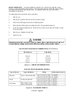
ELECTRICAL
WIRING
- Standard Units - The RotorChamp
compressor is factory wired for all starter to
motor and control connections for the voltage specified on the order. It is necessary only to connect the
unit starter to the correct power supply. The standard unit is supplied with an open drip-proof motor, a
NEMA 12 starter and control enclosure. See “Location” paragraph, page 12, for distance to nearest
obstruction on starter and control box sides of the unit.
WARNING
Electrical shock can cause injury or death. Open main disconnect switch, tag
and lockout before working on starter/control box.
GROUNDING
- Equipment must be grounded in accordance with Section 250 of the National Electrical
Code.
WARNING
Failure to properly ground the compressor package could result in controller
malfunction.
Summary of Contents for ROTORCHAMP EWF99C-100
Page 7: ...13 11 614 Page 7 Figure 1 2 PACKAGE ILLUSTRATION AIR COOLED 309EWF797 A Ref Drawing ...
Page 8: ...13 11 614 Page 8 Figure 1 3 PACKAGE ILLUSTRATION WATER COOLED 310EWF797 A Ref Drawing ...
Page 9: ...13 11 614 Page 9 Figure 1 4 AIR COOLED SCHEMATIC 307EWF797 A Ref Drawing ...
Page 10: ...13 11 614 Page 10 Figure 1 5 WATER COOLED SCHEMATIC 308EWF797 A Ref Drawing ...
Page 29: ...13 11 614 Page 29 Figure 4 2 FLOW CHART FOR SETUP PROGRAMMING 300EWC1255 Ref Drawing ...
Page 43: ...13 11 614 Page 43 303EWF546 A Ref Drawing Page 2 of 2 ...
Page 45: ...13 11 614 Page 45 304EWF546 A Ref Drawing Page 2 of 2 ...
Page 47: ...13 11 614 Page 47 305EWF546 A Ref Drawing Page 2 of 2 ...


