13-11-614 Page 26
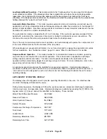
Remaining blowdown and auto times are only available in Low Demand, Automatic, and Sequence
modes, as appropriate.
If no keys are pressed for 5 seconds, the display will revert to its normal mode.
The display is also used as a service reminder for normal maintenance items. If service is recommended,
the yellow LED next to the service symbol will come on, and a message will alternate with the normal
lower line message. These messages are intended to advise of conditions which may lead to a
shutdown.
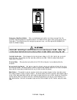
If a protective shutdown occurs, the red LED next to the shutdown symbol will be on and the top line of
the display will indicate “SHUTDOWN.” The lower line will indicate the cause of the shutdown.
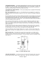
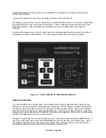
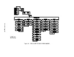
Figure 4-1 – AUTO SENTRY W CONTROLLER DISPLAY
SERVICE ADVISORIES
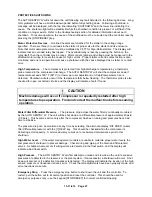
The AUTO SENTRY W controller turns on an advisory when it detects operation which needs service
attention, but does not warrant shutting down the compressor. Some of these are normal maintenance
procedures, and are intended to serve as a reminder to perform routine service. Others are conditions
which can reduce the maximum compressor performance. It will remain in effect until reset. Check the
display during routine inspections, and perform maintenance as suggested. Refer to the troubleshooting
section for detailed information about each advisory.
Temperature advisories may be cleared while the unit is running by simply pressing the [ENTER] key. To
reset the service advisories, press the [STOP/RESET] key to stop operation of the compressor. After it
has stopped, disconnect power and service as required. After servicing, restore power and reset the
controller as indicated in the programming / maintenance section below.
Summary of Contents for ROTORCHAMP EWF99C-100
Page 7: ...13 11 614 Page 7 Figure 1 2 PACKAGE ILLUSTRATION AIR COOLED 309EWF797 A Ref Drawing ...
Page 8: ...13 11 614 Page 8 Figure 1 3 PACKAGE ILLUSTRATION WATER COOLED 310EWF797 A Ref Drawing ...
Page 9: ...13 11 614 Page 9 Figure 1 4 AIR COOLED SCHEMATIC 307EWF797 A Ref Drawing ...
Page 10: ...13 11 614 Page 10 Figure 1 5 WATER COOLED SCHEMATIC 308EWF797 A Ref Drawing ...
Page 29: ...13 11 614 Page 29 Figure 4 2 FLOW CHART FOR SETUP PROGRAMMING 300EWC1255 Ref Drawing ...
Page 43: ...13 11 614 Page 43 303EWF546 A Ref Drawing Page 2 of 2 ...
Page 45: ...13 11 614 Page 45 304EWF546 A Ref Drawing Page 2 of 2 ...
Page 47: ...13 11 614 Page 47 305EWF546 A Ref Drawing Page 2 of 2 ...


