13-11-614 Page 28
Power Failure
- Following power interruptions, the controller will remain in a shutdown state (unless
programmed for auto restart).
External Device
- This input is used by a fixed-point (5 psig) oil pressure switch which shuts the
package down if the oil pressure does not exceed the set point within 10 seconds after starting the
compressor – an “External Device” message is factory-set to display with the oil pressure switch trip. An
expansion board is already provided to link the external device to the AUTO SENTRY W controller – the
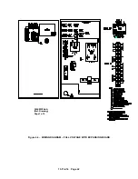
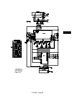
oil pressure switch is connected to terminals 9 and 31 – See Wiring Diagrams for details.
All external devices must have normally closed contacts which open to shut down the package.
Additional external devices must be wired in series with the oil pressure switch. Triggering anyone or
more of the external devices will be confirmed by a single message at the controller display; thus, multiple
triggerings must be locally identified and/or reset. Other messages are available (e.g., high vibration,
phase relay, low voltage relay and water pressure), but to avoid confusion, it is recommended that the
generic “external device” be used if additional devices are employed.
CAUTION
The PLC must be operating (e.g., the run/stop mode switch must be in the run
position) to allow the package compressor to start.
Other Shutdowns
- The controller runs continuous diagnostic checks of its own operation and the
sensors to which it is connected. Refer to the service section for a complete listing of shutdowns and
remedial actions.
Summary of Contents for ROTORCHAMP EWF99C-100
Page 7: ...13 11 614 Page 7 Figure 1 2 PACKAGE ILLUSTRATION AIR COOLED 309EWF797 A Ref Drawing ...
Page 8: ...13 11 614 Page 8 Figure 1 3 PACKAGE ILLUSTRATION WATER COOLED 310EWF797 A Ref Drawing ...
Page 9: ...13 11 614 Page 9 Figure 1 4 AIR COOLED SCHEMATIC 307EWF797 A Ref Drawing ...
Page 10: ...13 11 614 Page 10 Figure 1 5 WATER COOLED SCHEMATIC 308EWF797 A Ref Drawing ...
Page 29: ...13 11 614 Page 29 Figure 4 2 FLOW CHART FOR SETUP PROGRAMMING 300EWC1255 Ref Drawing ...
Page 43: ...13 11 614 Page 43 303EWF546 A Ref Drawing Page 2 of 2 ...
Page 45: ...13 11 614 Page 45 304EWF546 A Ref Drawing Page 2 of 2 ...
Page 47: ...13 11 614 Page 47 305EWF546 A Ref Drawing Page 2 of 2 ...


