13-11-614 Page 31
6. In the top line, “
AUTO TIME
” is displayed. The bottom line will indicate a time between 5 and 20
minutes. It too, is factory set at 10 minutes. Its function is to prevent too frequent motor starting, and
to allow the motor a ‘cool-down’ period before stopping.
7. In the top line, “
REMOTE STOP
” is displayed. The bottom line indicates either “TIMED” or
“IMMEDIATE”. Refer to the description of “Remote On/Off” later in this section for additional details.
Select the desired response to the remote input and press [ENTER] to proceed.
8. This completes the operational adjustments. The controller will return to the main adjustments menu.
Maintenance Adjustments
1.
If any service advisories are in effect (yellow ADVISORY indicator is on), they will be displayed on
the top line. The bottom line indicates “
LEAVE ADVISORY
” (do not reset) or “
CLEAR ADVISORY
”
(turn it off). Select the desired action and press [ENTER] to proceed.
2.
The top line displays “
NEXT RELUBE
” and the hours remaining are displayed on the bottom line.
Press the [+] or [-] keys to switch to the lubrication change interval (see UNIT SETUP) if service was
performed early. Press [ENTER] to proceed.
3.
This completes the maintenance adjustments. The controller will return to the main adjustments
menu.
Sequence Adjustments
See “SEQUENCING COMPRESSORS WITH THE AUTO SENTRY W, page 33
,
for more details on
setting up and optimizing a sequenced compressor installation.
1.
In the top line, “
NUM OF SEQ UNITS
” is displayed. The bottom line will indicate a number in the
range of one through eight. This will be factory set at “1”. This should be set to a number
corresponding to the number of compressors that are currently installed on this air system that also
have AUTO SENTRY W controllers. It should be noted that all AUTO SENTRY W compressors on
the system must have the same number programmed here to operate correctly in SEQUENCE
mode. Adjust as required, and press [ENTER] to proceed.
NOTICE
Setting the value in Step 1 to one indicates that no sequencing is to take place.
Consequently, Steps 2, 3 & 4, which relate to sequencing, are skipped by the
Auto Sentry W; the controller will return to the main adjustments menu.
2.
In the top line, “
UNIT NUMBER
” is displayed. The bottom line will again indicate a number of one
through eight and be factory set at “1”. Each AUTO SENTRY W in a sequenced system must have
a unique number here. The sequence mode will not function if two or more compressors have the
same UNIT NUMBER. The most efficient machine-to-machine communications will occur when the
lowest possible numbers are used. Example: 1, 2, and 3 for a three compressor installation.
All other settings should normally be the same for all units.
3.
In the top line, “
TRANSFER INTERVAL
” is displayed. The bottom line will indicate a number of
hours in the range of 1 to 5000. It is factory set at 24. This is the number of hours that this machine
will stay in the role of “master” or ”lead” compressor.
Normally it is desirable to set this to the same value on all sequenced units to equalize running
hours. Different values may be programmed, if desired, to help equalize hours.
Summary of Contents for ROTORCHAMP EWF99C-100
Page 7: ...13 11 614 Page 7 Figure 1 2 PACKAGE ILLUSTRATION AIR COOLED 309EWF797 A Ref Drawing ...
Page 8: ...13 11 614 Page 8 Figure 1 3 PACKAGE ILLUSTRATION WATER COOLED 310EWF797 A Ref Drawing ...
Page 9: ...13 11 614 Page 9 Figure 1 4 AIR COOLED SCHEMATIC 307EWF797 A Ref Drawing ...
Page 10: ...13 11 614 Page 10 Figure 1 5 WATER COOLED SCHEMATIC 308EWF797 A Ref Drawing ...
Page 29: ...13 11 614 Page 29 Figure 4 2 FLOW CHART FOR SETUP PROGRAMMING 300EWC1255 Ref Drawing ...
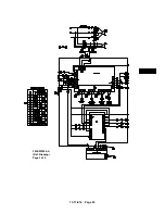
Page 43: ...13 11 614 Page 43 303EWF546 A Ref Drawing Page 2 of 2 ...
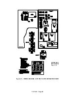
Page 45: ...13 11 614 Page 45 304EWF546 A Ref Drawing Page 2 of 2 ...
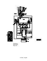
Page 47: ...13 11 614 Page 47 305EWF546 A Ref Drawing Page 2 of 2 ...

