13-11-614 Page 48
SECTION 5
LUBRICATION
COMPRESSOR OIL SYSTEM
- The oil reservoir is filled with oil at the factory before shipment. A tag
on the reservoir fill cap indicates the type of oil in the reservoir as it left the factory.
RECOMMENDED LUBRICANT
- Champion compressors are factory filled with RotorLub™ lubricants.
These lubricants are formulated to the highest quality standards and are factory authorized, tested and
approved for use in rotary screw compressors.
RotorLub lubricants are available through your authorized Champion compressor distributor.
OIL SPECIFICATIONS
- The airend reservoir is factory filled with RotorLub lubricant. A lubricant
analysis program for a periodic check of lubricant quality and remaining life can maximize the change
interval.
Material Safety Data Sheets (MSDS) are available for all RotorLub lubricants from your authorized
Champion distributor or by calling 815-875-3321.
CAUTION
Use of improper lubricants will cause damage to equipment. Do not mix
different types of lubricants or use inferior lubricants.
CAUTION
Improper equipment maintenance with use of synthetic lubricants will damage
equipment. Oil change intervals must be adhered to for maximum compressor
protection and efficiency. See “Maintenance Schedule”, page 60
WARNING
High temperature operation can cause damage to equipment or personal injury.
Do not repeatedly restart the unit after high temperature stops the operation.
Find and correct the malfunction before resuming operation.
COMPRESSOR OIL SYSTEM CHECK -
Oil pressure – 15 to 25 psig (1.0 to 1.8 bar) indicated by the
local oil pressure gauge, after the unit has reached normal operating temperature.
Summary of Contents for ROTORCHAMP EWF99C-100
Page 7: ...13 11 614 Page 7 Figure 1 2 PACKAGE ILLUSTRATION AIR COOLED 309EWF797 A Ref Drawing ...
Page 8: ...13 11 614 Page 8 Figure 1 3 PACKAGE ILLUSTRATION WATER COOLED 310EWF797 A Ref Drawing ...
Page 9: ...13 11 614 Page 9 Figure 1 4 AIR COOLED SCHEMATIC 307EWF797 A Ref Drawing ...
Page 10: ...13 11 614 Page 10 Figure 1 5 WATER COOLED SCHEMATIC 308EWF797 A Ref Drawing ...
Page 29: ...13 11 614 Page 29 Figure 4 2 FLOW CHART FOR SETUP PROGRAMMING 300EWC1255 Ref Drawing ...
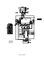
Page 43: ...13 11 614 Page 43 303EWF546 A Ref Drawing Page 2 of 2 ...
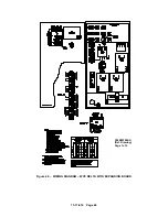
Page 45: ...13 11 614 Page 45 304EWF546 A Ref Drawing Page 2 of 2 ...
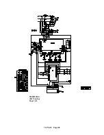
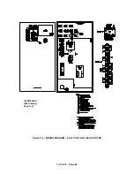
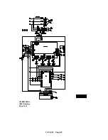
Page 47: ...13 11 614 Page 47 305EWF546 A Ref Drawing Page 2 of 2 ...

