13- 11- 603
Page 10
enclosure through louvers in the side panels, through
the aftercooler and exhausted through the heat ex-
changer at the top of the unit. The air-- cooled unit with
the standard enclosure requires sufficient flow,
FIGURE 2-- 2, page 9, for the compressor water/after-
cooling system and for electric motor cooling. Do not
block the air flow to and from the unit. Allow three and
one-- half (3-- 1/2) feet to the nearest obstruction on the
control box end of the unit. Allow three (3) feet to the
nearest obstruction above and on other sides of unit.
For continuous efficiency, the heat exchanger and af-
tercooler cores must be periodically cleaned with either
vacuum or compressed air. If wet cleaning is required,
shield the motor and spray on a mild soap solution, then
flush with clean water.
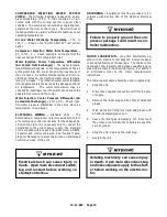
For copper water coolers, do not use
any cleaning solution that is not com-
patible with copper. Use of improper
solution may result in damage to the
cooler.
FOUNDATION
-- The Champion Rotary Screw com-
pressor requires no special foundation, but should be
mounted on a smooth, solid surface. Whenever pos-
sible install the unit near level. Temporary installation
may be made at a maximum 10
_
angle lengthwise or
10
_
sidewise.
Mounting bolts are not normally required. However,
installation conditions such as piping rigidity, angle of
tilt, or danger of shifting from outside vibration or mov-
ing vehicles may require the use of mounting bolts and
shims to provide uniform support for the base.
OIL RESERVOIR DRAIN
-- The oil drain plug is located
at the bottom of the discharge end of the compressor.
(See FIGURE 5-- 1, page 40.)
ENCLOSURE
-- The compressor, electric motor, water
cooler and aftercooler are mounted inside the enclo-
sure.
Service doors are provided for maintenance access.
Be sure to allow enough space around the unit for the
doors to be opened and removed as necessary for ser-
vice procedures. The enclosure doors are held by two
latches and lift away from the enclosure. The air filter,
water filters, and water treatment cartridge are easily
accessible through a side or end door.
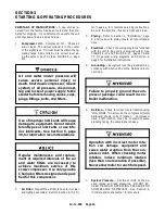
Do not operate the compressor with
the belt guard removed. Exposed
belts may cause injury to personnel.
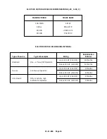
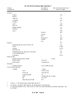
COMPRESSOR WATER SPECIFICATION
-- The
compressor initial fill and make-- up water must meet
the United States Environmental Protection Agency
National Primary and Secondary Drinking Water Reg-
ulations (See Table, page 15.) By requiring potable
water fit for human consumption, a quality level is de-
fined which is most generally readily available.
Backflow
Preventers
must
be
installed on the potable water supply
line to the compressor to preventhigh
pressure air from blowing into the wa-
ter supply.
Use of compressor initial fill and
make--up water not meeting all water
specification standards noted may
result in contamination of the dis-
charge air stream.
Compressor water seal leakage may
occur. You must have potable make--
up water available.
Water may no longer be potable after
use in the compressor.
Summary of Contents for ROTORCHAMP RCOF20
Page 13: ...13 11 605 Page 4 FIGURE 1 6 AIR WATER SCHEMATIC 300EWC797 B Ref Drawing ...
Page 16: ...13 11 605 Page 7 DECALS 206EAQ077 300EWC077 301EWC077 211EAQ077 207EAQ077 ...
Page 17: ...13 11 605 Page 8 DECALS 216EAQ077 206EWD077 222EAQ077 221EAQ077 208EAQ077 ...
Page 31: ...13 11 605 Page 22 FIGURE 4 2 FLOW CHART FOR SET UP PROGRAMMING 300EWC1255 Ref Drawing ...
Page 41: ...13 11 605 Page 32 FIGURE 4 6 CONTROL TUBING SCHEMATIC 300EWC797 B Ref Drawing ...
Page 45: ...13 11 605 Page 36 FIGURE 4 10 WIRING DIAGRAM FULL VOLTAGE 301EWC546 A Ref Drawing ...
Page 46: ...13 11 605 Page 37 FIGURE 4 11 WIRING DIAGRAM WYE DELTA 302EWC546 A Ref Drawing ...
Page 47: ...13 11 605 Page 38 FIGURE 4 12 AUTO SENTRY W CONTROLLER DISPLAY ...
Page 49: ...13 11 605 Page 40 FIGURE 5 1 OIL LEVEL SIGHT GLASS 306EWC797 A Ref Drawing ...
Page 50: ...13 11 605 Page 41 FIGURE 5 2 FLOW DIAGRAM AIR COOLED 300EWC797 A Ref Drawing ...


