13- 11- 605
Page 27
bers. Number 2 becomes number 1, the new master,
number 3 becomes number 2, etc.
It should be noted also that whenever the master de-
tects a missing rotation number, such as when a com-
pressor is turned off that was previously in the rotation,
it will automatically ’close the gap’ by decrementing the
rotation numbers of all compressors whose rotation
numbers were greater than the missing number. Like-
wise, if for whatever reason, the master compressor
fails to carry out its role, all lag compressors begin
decrementing their rotation number until a new master
is established. Regardless of the scenario, the end re-
sult will always be that the compressors that remain in
rotation will always end up with the lowest possible
rotation numbers.
Other Features
Any air system will exhibit pressure differences from
one point to the next. Even a well designed multi-- com-
pressor installation will show ‘minor’ pressure varia-
tions between one compressor’s discharge point and
another compressor’s discharge. These points will
also vary from the central system (normally the air stor-
age receiver). The AUTO SENTRY
R
-- W sequencing
system is designed to tolerate minor variations. These
pressure differences wreak havoc with conventional
sequencers. If a central sequencer is used, it will be
sensing a lower pressure than is seen at each com-
pressor. With such systems, there is always a chance
that the sequencer could cause a compressor to over
pressure due to this pressure drop. The alternative has
been to set the central sequencer to a lower pressure
to prevent this or allow local override of the sequencer
by the local pressure control, neither of which is desir-
able in the scheme of maintaining plant pressure effi-
ciently with sequencing. The AUTO SENTRY
R
-- W se-
quencing system will automatically adjust the system
to prevent over pressures in any individuals.
The AUTO SENTRY
R
-- W sequencing system lets
each compressor control itself independently between
setpoints derived to cause staggered operation, or se-
quencing. The aforementioned pressure drops can
also cause derogatory effects (mainly skewed, or out
of sequence operation) to the sequencing algorithm
used by the AUTO SENTRY
R
-- W.
Since these pressure variations are not constant (they
will vary due to demand changes, compressor load /
unload changes, and number of compressors running),
any scheme to compensate for the pressure variations
must be dynamic. The exclusive dynamic unload point
control feature enables this error correction scheme to
be accomplished rather easily.
Here’s how it works: The master continually receives
system pressure values from every machine in the se-
quence rotation. The values are averaged and this av-
erage is then distributed to all lag compressors. All
compressors, lead and lag, then compare their local
pressure reading to the average and adjust their PSET
by the amount of error. The effect is that all compres-
sors are controlling to a single pressure reading, a
reading that is not one that is picked up somewhere re-
moved from the compressor, but an average of actual
discharge pressures.
It should be noted that the pressure displayed on the
top line by all sequenced compressors is this average.
CONNECTION OF EXPANSION BOARD AND EX-
TERNAL CONTROL CIRCUITS
The AUTO SENTRY
R
-- W controller has a connection
port for use with an expansion board, part number
301EWC1173. This provides interconnection points
for external controls and indicators. This allows simple
connection to remote controls and indicators, or in-
tegration into any plantwide controls system. The ex-
pansion board also provides the data port for commu-
nications in sequencing.
The expansion board is
pre-- installed on any unit with factory-- mounted wye--
delta starters.
To install on other units, stack the expansion board over
the main control board, and mount with the hardware
included. Use the cable to connect the expansion
board to the main board. The AUTO SENTRY
R
-- W
controller automatically detects the presence or ab-
sence of the expansion board, but 120V input circuits
must be connected to the expansion board for proper
operation. Spare terminals are provided at the control
terminal strip in the box for connection of the following
120v circuits. Connect either to unused existing termi-
nals, or mark blank terminal locations for new points
shown.
Connect from the expansion board plug to terminals as
follows:
Expansion Plug
Panel Terminal
J1-- 1
8 (existing)
J1-- 2
no connection
J1-- 3
23 (new)
J1-- 4
24 (new)
J1-- 5
10 (existing)
J1-- 6
21 (new)
J1-- 7
20 (new)
J1-- 8
19 (new)
Summary of Contents for ROTORCHAMP RCOF20
Page 13: ...13 11 605 Page 4 FIGURE 1 6 AIR WATER SCHEMATIC 300EWC797 B Ref Drawing ...
Page 16: ...13 11 605 Page 7 DECALS 206EAQ077 300EWC077 301EWC077 211EAQ077 207EAQ077 ...
Page 17: ...13 11 605 Page 8 DECALS 216EAQ077 206EWD077 222EAQ077 221EAQ077 208EAQ077 ...
Page 31: ...13 11 605 Page 22 FIGURE 4 2 FLOW CHART FOR SET UP PROGRAMMING 300EWC1255 Ref Drawing ...
Page 41: ...13 11 605 Page 32 FIGURE 4 6 CONTROL TUBING SCHEMATIC 300EWC797 B Ref Drawing ...
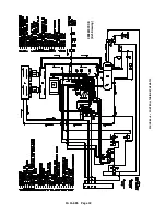
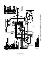
Page 45: ...13 11 605 Page 36 FIGURE 4 10 WIRING DIAGRAM FULL VOLTAGE 301EWC546 A Ref Drawing ...
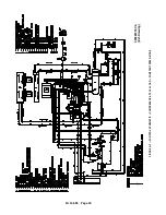
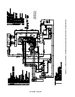
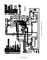
Page 46: ...13 11 605 Page 37 FIGURE 4 11 WIRING DIAGRAM WYE DELTA 302EWC546 A Ref Drawing ...
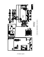
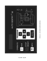
Page 47: ...13 11 605 Page 38 FIGURE 4 12 AUTO SENTRY W CONTROLLER DISPLAY ...
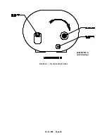
Page 49: ...13 11 605 Page 40 FIGURE 5 1 OIL LEVEL SIGHT GLASS 306EWC797 A Ref Drawing ...
Page 50: ...13 11 605 Page 41 FIGURE 5 2 FLOW DIAGRAM AIR COOLED 300EWC797 A Ref Drawing ...

