13- 11- 605
Page 51
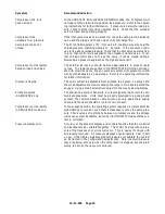
Message
Action Needed
HIGH RESVR PRESS
Pressure in excess of the programmed high pressure limit has been de-
tected. This shutdown will occur if a loss of pneumatic controls occurs.
Check the inlet valve, all control piping, solenoid valves, and all other con-
trol devices to find the cause for the inlet valve not closing. Other possible
causes are loose connections to the transducer, electrical noise and tran-
sients, or improper setting of the high pressure limit.
HIGH SYSTEM PRESS
Pressure in excess of the programmed high pressure limit has been de-
tected. The most likely cause is other, higher pressure compressors on
the same air system; separate these from this compressor unit. Other
possible causes are loose connections to the transducer, electrical noise
and transients, or improper setting of the high pressure limit.
HIGH VIBRATION
120 volts has been removed from J1-- 4 of the expansion board. This is
normally jumpered directly to terminal 9, but the jumper may be removed
to add a field installed shutdown switch. Reset the external switch.
HIGH WATER LEVEL
120 volts has been removed from terminal 5 of the terminal strip. This nor-
mally indicates that a high water level in the reservoir has opened switch
LS3 of the float switch assembly. Check that the drain is clear and that
the drain solenoid valve is functioning properly. This may also indicate a
loose connection along wire 5.
LOW DISCH TEMP
The temperature, as measured at the airend discharge, has fallen below
freezing. Repair room heating to prevent
further damage to the unit.
LV RELAY
120 volts has been removed from J1-- 4 of the expansion board. This is
normally jumpered directly to terminal 9, but the jumper may be removed
to add a field installed shutdown switch. Reset the external switch.
MOTOR CONTACT
The controller has attempted to turn off the compressor, but is still receiv-
ing a return signal from the starters’ auxiliary contacts. Check that the
starter operates freely and that the contact blocks are properly installed
on the starter.
MOTOR OVERLOAD
One of the motor overload relays within the electrical control box has
tripped, indicating high motor shaft load, low voltage, or excessive imbal-
ance in the incoming power. Disconnect and lock out power, open the box,
and press the reset buttons one at a time -- the tripped one will click when
reset. Measure motor amps, and take corrective actions to get all currents
within the motor nameplate rating. If overloads had not tripped, check for
the cause that 120 volts was removed from connector 5-- 3 of the control-
ler.
MOTOR STARTER
The controller has attempted to start the compressor, but did not receive
a return signal from the starter’s auxiliary contact. If the starter does not
pick up when attempting to start, check that connector 6 of the controller
is plugged in firmly, and check the starter coil. If the starter does pick up,
but this message appears, check that the auxiliary contact block is proper-
ly installed on the starter and wired to connector 1, terminal 4.
OPEN THERMISTOR
The controller has detected an open connection to the airend discharge
thermistor. This normally indicates a loose or broken connection at the
controller connector 7; check and correct the connection. This could also
be indicating a broken wire or thermistor probe.
OPEN XDUCER
Signal voltage has fallen too low at transducer: (A) Final discharge, (B)
Water Injection, or (C) Reservoir. This usually indicates a loose connec-
tion of the red wire to the transducer or a defective transducer. Check con-
nections, or replace transducer if necessary.
PHASE RELAY
120 volts has been removed from J1-- 4 of the expansion board. This is
normally jumpered directly to terminal 9, but the jumper may be removed
to add a field installed shutdown switch. Reset the external switch.
Summary of Contents for ROTORCHAMP RCOF20
Page 13: ...13 11 605 Page 4 FIGURE 1 6 AIR WATER SCHEMATIC 300EWC797 B Ref Drawing ...
Page 16: ...13 11 605 Page 7 DECALS 206EAQ077 300EWC077 301EWC077 211EAQ077 207EAQ077 ...
Page 17: ...13 11 605 Page 8 DECALS 216EAQ077 206EWD077 222EAQ077 221EAQ077 208EAQ077 ...
Page 31: ...13 11 605 Page 22 FIGURE 4 2 FLOW CHART FOR SET UP PROGRAMMING 300EWC1255 Ref Drawing ...
Page 41: ...13 11 605 Page 32 FIGURE 4 6 CONTROL TUBING SCHEMATIC 300EWC797 B Ref Drawing ...
Page 45: ...13 11 605 Page 36 FIGURE 4 10 WIRING DIAGRAM FULL VOLTAGE 301EWC546 A Ref Drawing ...
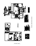
Page 46: ...13 11 605 Page 37 FIGURE 4 11 WIRING DIAGRAM WYE DELTA 302EWC546 A Ref Drawing ...
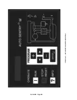
Page 47: ...13 11 605 Page 38 FIGURE 4 12 AUTO SENTRY W CONTROLLER DISPLAY ...
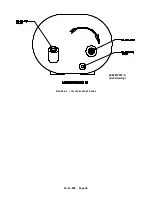
Page 49: ...13 11 605 Page 40 FIGURE 5 1 OIL LEVEL SIGHT GLASS 306EWC797 A Ref Drawing ...
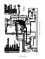
Page 50: ...13 11 605 Page 41 FIGURE 5 2 FLOW DIAGRAM AIR COOLED 300EWC797 A Ref Drawing ...

