Page 3
leave this terminal disconnected. Do not connect the Ground terminal to anything except the
ground connection from your turntable.
•
In lieu of the built-in RIAA Output Module, the Ground will be mounted on the chassis in the
LEFT RIAA output position. The Ground chassis position shown in the figure will be occupied by
the 5-pin power connector for the optional external RCM (RIAA Correction Module).
Power-Up (Initial) Configuration
•
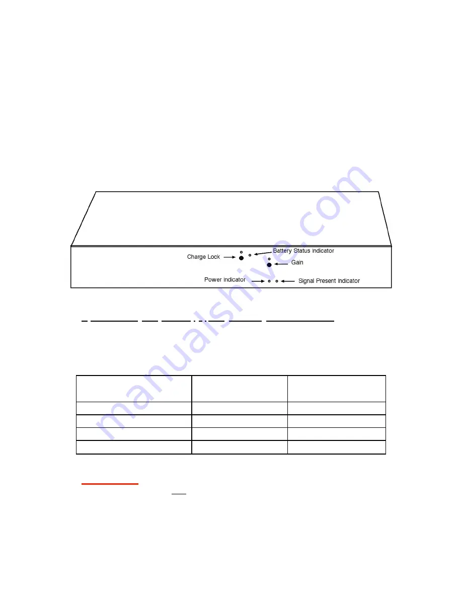
Charge Lock
: Initialize indicator by pressing button after first connecting power, if not
illuminated.
•
Sig
indicator: initially on, extinguishing after several minutes.
(If the Sig indicator does not
extinguish, be sure to check if an input connection has become loose or dislodged.)
•
Gain
: must be initialized after connecting power, see below.
Gain Adjustment
Upon connecting the power supply, the gain setting must be initialized
by pressing the front
panel Gain button several times, until the Low (Light Blue) indicator appears. The gain setting
will be preserved as long as power is supplied (and, as indicated below, in the AGM Rechargeable
Battery Operation and Charging section, the Seta should normally be maintained in a powered
state).
WARNING!
Always make changes to the Gain Setting at a reduced or muted
playback volume,
to keep
loud
transients (thumps) from playing through the loudspeak-
ers. The Seta gain control isn’t meant to be adjusted frequently. It’s designed for ease (in
contrast to having internal jumpers or switches) of setting the phono preamplifier gain, to
provide the optimum input signal level for your digital audio interface and phono
cartridge. With that purpose in mind, any circuitry for preventing “thumps” that also
could compromise audio quality was omitted in the Seta design.
Indicator Color / Gain
Light Blue (Low)
Blue (Medium)
Violet (Medium High)
Red (High)
Gain (Flat Outputs)
43 dB
46 dB
49 dB
53 dB
Gain (RIAA Outputs)
55 dB
58 dB
61 dB
65 dB


