PRESSURE REGULATOR
The spray tank and the pressure chamber are separate compartments in a Chapin
Sprayer. Therefore, pressure is maintained in a separate pressure chamber within
the unit and is built to with stand normal operating pressure. For additional
safety an internal pressure control valve has been
fi
tted to the cylinder (with four
pressure settings that are adjustable for different needs (see diagram).
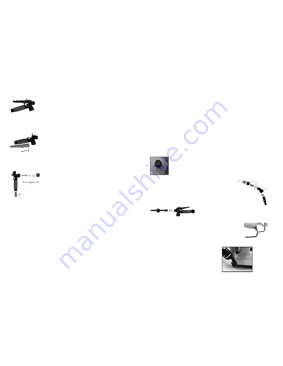
REMOVING THE ADJUSTABLE NOZZLE
Unscrew the nozzle cap
(1)
from the nozzle body
(3)
with retaining
nut
(2)
fastened tightly to the elbow
(5)
. Unscrew the retaining
nut
(2)
. Push the nozzle body
(3)
with the nozzle gasket
(4)
out of
the retaining nut
(2)
. To reinstall the nozzle, reverse the above
instructions.
ASSEMBLY INSTRUCTIONS FOR WAND
1. Make sure the o-ring is installed on the end of the wand.
Insert the wand into shut-off valve.
2. Turn and tighten the screw cap clock-wise onto the shut-off valve.
INSTALLING THE PUMP LEVER
The sprayer includes all hardware necessary for installing the
pump lever. The pump lever can be mounted on either end of the
shaft. To install the pump lever place the lever handle (C) onto
the shaft (A). Align the bolt hole and install the bolt (E) and nut
(F) and tighten.
INSTALLING THE SHOULDER STRAP
The top of the shoulder straps
are attached to the tank. Attach
the lower end of the straps by
fastening the strap hooks to the
metal frame between where the
frame exits the tank and curves
around.
APPLICATIONS & USE FOR YOUR CHAPIN SPRAYER
Avoid using a sprayer for general cleaning purposes if plant protection or herbicide
chemicals have already been used in the sprayer if possible. If a sprayer has been used for
plant protection or as an herbicide, clean the sprayer completely (see page 4) before using.
Plant Food:
Use different spray patterns for optimum foliage feeding or for fungicide and
pesticide application.
Herbicides:
Reduce weeds and unwanted plants but avoid using the same sprayer for
plant feeding or protection without thoroughly cleaning (see pg.4) the sprayer
fi
rst.
General Household Use:
Apply detergents, vinegar, cleaning solutions, warm water (do not
exceed 120°F/49°C) or nontoxic household cleaning chemicals for carpets,
fl
oors, walls, glass,
counter tops and ceilings. DO NOT use sprayer that has been used with herbicides, pesticides
or other toxic chemicals for household applications.
General Outdoor Use:
Use the sprayer for cleaning windows or with a detergent for general
purpose cleaning. Other applications include wood preservatives, waxes, water proo
fi
ng, and
diluted household bleach (max. 1 part household bleach to 9 parts water solution).
SPRAYER COMPONENTS & USE INFORMATION
C. Pump Lever
A. Shaft
E, F. Bolt, Nut
2E
15psi
30psi 45psi
60psi
1. Nozzle Cap
3. Nozzle
2. Retaining Nut
5. Elbow
4. Nozzle
Gasket
1) Assembled shut-off valve (Figure 19).
2) Remove the retaining pin (A) (Figure 20). Place the notched
end of the retaining pin on a hard surface and push down.
Remove the retaining pin when it pops up and slide the handle
off the valve.
3) Remove the screw cap, spring, and valve body. (B) (Figure 21).
Replace worn O-rings and parts. Lubricate the O-rings and
reassemble by reversing the steps above. Place the handle groove
in the slotted area of the valve body and make sure the locking clip
is positioned correctly. Insert the retaining pin. Push down on the
handle and release repeatedly to distribute the lubricant evenly.
(C) Check filter in end of shut-off valve for debris. Remove filter
and flush with water to clean out.
DISASSEMBLING AND REPAIRING THE SHUT OFF VALVE
Figure 19
Figure 20
1) Chapin backpack sprayers come with a shut-off valve, wand, and elbow/nozzle assembly. If
the sprayer has an adjustable plastic nozzle unscrew the nozzle cap
fi
rst. Remove the nut,
nozzle and nozzle O-ring,
fi
lter and
fi
lter O-ring, and elbow from the wand. Remove the O-
ring from the elbow and discard. To reassemble, put the nut, nozzle and new nozzle O-ring,
fi
lter and new
fi
lter O-ring, elbow and new elbow O-ring back on in that order. Reassemble
the retaining nut to the elbow. The metal screen
fi
lters with gaskets do not require an O-ring
on either side.
2) Remove the wand from the shut-off valve assembly. Remove the O-ring from the wand and
replace with a new O-ring and set the wand aside.
3) Reinstall the wand to the shut-off valve and reinstall the elbow to the wand.
4) Test with water before using.
REPAIRING THE WAND / NOZZLE ASSSEMBLY
9E
Figure 21
B
A
C


