Page 13
3.
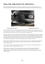
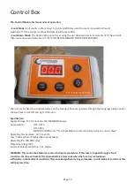
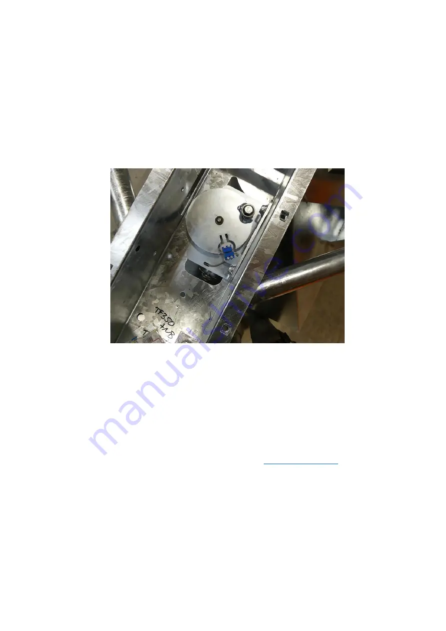
In the Picture below you can see the sensor (with the wire) and the magnet (fitted to the disc) are facing each
other with approximately 2mm gap between them. The sensors also need to be aligned vertically (so that they
are approximately level with each other).
If required you can bend the sensor support bracket up or down to get vertical alignment, and you can move
the sensor in or out on the slotted holes to get horizontal alignment.
FOR MACHINES USED WITH DUSTY FEED OR FEED WITH ADDITIVES SUCH AS MOLLASES, BUILD UP OF DIRT
CAN AFFECT THE SENSOR OPERATION
–
IN THIS CASE CLEAN WITH A LOW-PRESSURE WATER JET.
Consult the relevant parts diagram for the sensor part number if spares are required, alternatively contact
your distributor.
4.
Parts are re-fitted as a reverse of removal, taking care to ensure all bolts are secure and tight. If adjustments
have been made to the sensor, ensure the cable is secured with cable ties or similar to prevent accidental
damage.
Once this has been checked and all dirt removed, your problem should be resolved.
If the problem persists, please contact us 01288 308 149 or email us on
than happy to help.

