background image

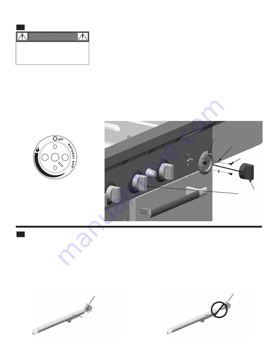
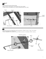
Pull the Tube Burner Control Knob off of Valve Stem. 

Remove two Screws and two Washers that secure Bezel to the Control Panel.  Save removed Bezel for converting back to LP Tank 

Gas.

Install new Natural Gas Bezel provided with Kit (see illustration below) in place of old Bezel onto Control Panel, and secure using 

previously removed Screws and Washers.  Assure proper alignment with control knob before fully tightening.  Note: New bezels will 

change the rotation for the control knob to properly control ignition and flames for your grill.  

Press Control Knob back onto Valve Stem.  Make adjustments needed to Bezel for free movement of Control Knob

Repeat for each Bezel.

B3

Tube Burner 

Control Knobs

Bezels

Valve

Stem

Lock Washers

Screws

Contr

ol Panel

B4

Reinstall Tube Burners

Insert Tube Burners into Firebox Burner holes over Valves with Ignitor Assembly downward, making sure Tube Burner engages Valve

properly.  See diagram below.

Secure Tube Burners to Burner Brackets with previously removed Hitch Pins.  Replace Carryover tubes and secure with Hitch Pins 

previously removed.  Reference illustration B1.

Incorrect

burner-to-valve

engagement

Correct

burner-to-valve

engagement

Tube Burner

Section B Con’t.

Bezel

WARNING

Bezels must be replaced one at a 
time.  Removing more than one bezel 
at a time may cause misalignment of 
manifold.

10 

Summary of Contents for 5729581

Page 1: ... Conversion Kit can be used ONLY with Dual Fuel grills If you have questions or need assistance during assembly please call To insure your satisfaction and for follow up service register your grill online at www grillregistration com 1 800 241 7548 USA or 1 800 387 6057 Canada ...

Page 2: ...uced when using this product contain chemicals known to the State of California to cause cancer birth defects and other reproductive harm 2 This product contains chemicals including lead and lead compounds known to the State of California to cause cancer birth defects or other reproductive harm Wash your hands after handling this product To Installer Assembler Leave these instructions with consume...

Page 3: ...WARNING Do not use hard metal piping of any kind to connect this type of grill to natural gas source Use only hose specified by manufacturer Using hard metal piping or convoluted metal tubing is an unsafe practice Movement of the grill can cause breakage of metal pipe CONNECTING YOUR GRILL TO THE NATURAL GAS SOURCE 1 A professionally installed shut off valve between the supply piping and the socke...

Page 4: ...s of 1 2 psig 3 5kPa The appliance must be isolated from the gas supply piping system by closing its individual manual shutoff valve during any pressure testing of the gas supply piping system at test pressures equal to or less than 1 2 psi 3 5kPa 4 PARTS LIST Key Qty Description Part No Note Illustrations are not to scale A C D 54 Black Dot B A 5 Main Sideburner Natural Gas Bezel 3499466 B 1 Orif...

Page 5: ... Driving Tool 3 54 Orifices Black Dot 1 1 45 Orifice Red Dot For Conversion Use Sections A C E Parts Required 5 Bezels 1 10 Hose 1 Orifice Driving Tool 4 1 30mm Orifices White Dot 1 1 45mm Orifice Red Dot For Conversion Use Sections A D E Parts Required 4 Bezels 1 10 Hose 1 Orifice Driving Tool 3 54 Orifice Black Dot 1 1 45MM Red Dot Model 463269411 Model 463269211 Model 463269311 Model 463269111 ...

Page 6: ...For Conversion Use Sections A F Parts Required 2 Bezels 1 10 Hose 1 Orifice Driving Tool Model 463269011 6 ...

Page 7: ...ns shown This manual covers a variety of grills styles use pictures as reference only Warming Rack Cooking Grates 2 or 3 depending on Unit purchased Heat Diffusers Lid Section A A2 Using a wrench not provided remove LP Regulator Hose Assembly from Manifold Connection Save removed LP Regulator Hose assembly for converting back to LP Tank Gas Your LP Regulator hose will be located under the Sideburn...

Page 8: ...e Assembly Manifold Connection A4 Leak Testing Natural Gas Hose Turn all grill knobs to OFF Brush soapy solution onto areas where bubbles are shown in picture If growing bubbles appear there is a leak Retighten connections If leak cannot be stopped do not try to repair Call Char Broil for replacement parts Natural Gas Hose Assembly Manifold Connection Leak test this connection 8 ...

Page 9: ...tch Pin Carryover Tube Burner Burner B2 Insert Orifice Driving Tool into Firebox Burner openings and unscrew Orifices from ends of Valves Save removed orifices for converting back to LP Tank Gas Replace with natural gas Orifices provided with Kit 1 25mm Orange Dot and tighten to valve end ensure Orifice is not cross threaded Valve Orifice Front of Firebox Orifice Firebox Burner Opening Orifice Dri...

Page 10: ...Valve Stem Make adjustments needed to Bezel for free movement of Control Knob Repeat for each Bezel B3 Tube Burner Control Knobs Bezels Valve Stem Lock Washers Screws Control Panel B4 Reinstall Tube Burners Insert Tube Burners into Firebox Burner holes over Valves with Ignitor Assembly downward making sure Tube Burner engages Valve properly See diagram below Secure Tube Burners to Burner Brackets ...

Page 11: ...tch Pin Carryover Tube Burner Burner C2 Insert Orifice Driving Tool into Firebox Burner openings and unscrew Orifices from ends of Valves Save removed orifices for converting back to LP Tank Gas Replace with natural gas Orifices provided with Kit 1 30mm White Dot and tighten to valve end ensure Orifice is not cross threaded Valve Orifice Front of Firebox Orifice Firebox Burner Opening Orifice Driv...

Page 12: ...Valve Stem Make adjustments needed to Bezel for free movement of Control Knob Repeat for each Bezel C3 Tube Burner Control Knobs Bezels Valve Stem Lock Washers Screws Control Panel C4 Reinstall Tube Burners Insert Tube Burners into Firebox Burner holes over Valves with Ignitor Assembly downward making sure Tube Burner engages Valve properly See diagram below Secure Tube Burners to Burner Brackets ...

Page 13: ...Hitch Pin Carryover Tube Burner Burner D2 Valve Orifice Front of Firebox Orifice Firebox Burner Opening Orifice Driving Tool Section D Orifice Driving Tool Insert Orifice Driving Tool into Firebox Burner openings and unscrew Orifices from ends of Valves Save removed orifices for converting back to LP Tank Gas Replace with natural gas Orifices provided with Kit 54 Black Dot and tighten to valve end...

Page 14: ...Valve Stem Make adjustments needed to Bezel for free movement of Control Knob Repeat for each Bezel D3 Tube Burner Control Knobs Bezels Valve Stem Lock Washers Screws Control Panel D4 Reinstall Tube Burners Insert Tube Burners into Firebox Burner holes over Valves with Ignitor Assembly downward making sure Tube Burner engages Valve properly See diagram below Secure Tube Burners to Burner Brackets ...

Page 15: ...ection E Using the provided Orifice Driving Tool unscrew the Orifice from the end of the Sideburner Valve Save removed Orifice and Orifice Driving Tool for converting back to LP Replace with natural gas Orifice provided with Kit 1 45mm Red Dot and tighten to valve end ensure Orifice is not cross threaded E2 Orifice Driving Tool Valve Orifice Orifice Driving Tool 15 ...

Page 16: ...lve Stem Sideburner control knob Valve stem Washer Screw Bezel Section E Con t Bezel Return Sideburner to Shelf Make sure Burner engages Sideburner Valve See illustration below for correct burner to valve engagement Secure Burner to Shelf with Wingnut Place Sideburner Grate onto Sideburner Pan E4 Valve Sideburner Wingnut Sideburner Grate Sideburner CORRECT BURNER TO VALVE ENGAGEMENT Reinstall Heat...

Page 17: ...itch Pin Hitch Pin Carryover Tube Burner Burner F2 Insert Orifice Driving Tool into Firebox Burner openings and unscrew Orifices from ends of Valves Save removed orifices for converting back to LP Tank Gas This grill is designed to work with Natural Gas once Orifices are removed No replacement Orifice is necessary Valve Orifice Front of Firebox Orifice Firebox Burner Opening Orifice Driving Tool S...

Page 18: ...Valve Stem Make adjustments needed to Bezel for free movement of Control Knob Repeat for each Bezel F3 Tube Burner Control Knobs Bezels Valve Stem Lock Washers Screws Control Panel F4 Reinstall Tube Burners Insert Tube Burners into Firebox Burner holes over Valves with Ignitor Assembly downward making sure Tube Burner engages Valve properly See diagram below Secure Tube Burners to Burner Brackets ...

Page 19: ...ighting section of Grill Use and Care Open Natural Gas Valve to full open position Call gas company TROUBLESHOOTING EMERGENCIES If a gas leak cannot be stopped or a fire occurs due to gas leakage call the fire department Emergencies Gas leaking from cracked cut burned hose Possible Cause Damaged hose Prevention Solution Turn off gas at at source If anything but burned replace parts If burned disco...

Page 20: ...NOTES ...
Reviews: