12
19
13
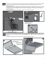
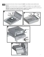
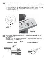
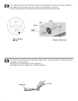
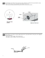
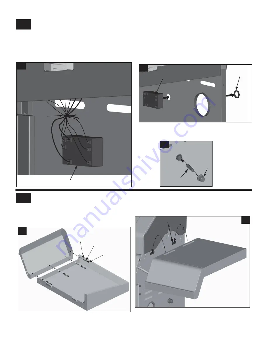
Inside of the cart, connect the wires from burner electrodes into the back of Electronic Ignition module. Total (5) connections.
Note: Switch terminals are larger than electrode terminals and should only be installed in location shown as (a),(b).
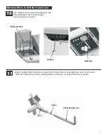
Connect the two wires [(a) and (b)] from switch wiring harness into the back of Electronic Ignition module. Total (2)
connections, shown
A
.
1
(a)
(b)
2
3
4
5
Electronic ignition module
+
-
Cap
AA battery
Right side panel
C
A
B
Nut
Electronic ignition
Tie wrap
Right side panel
module
NOTE: Wires omitted for
clarity of illustration
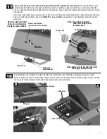
Unscrew the cap and nut from electronic ignition module. Attach electronic ignition module to the cart right side panel
with the nut, shown
B
.
Insert AA battery into ignition module, negative (
–
) end first. Then put on the cap, shown
C.
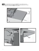
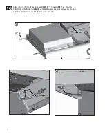
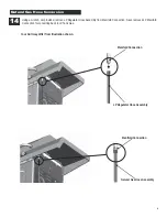
Attach right side control panel to right side shelf using four
#10-24x3/8”
screws,
5mm
lock washers and
5mm
flat washers,
shown
A
.
Insert flange on right side shelf into side shelf brackets on right side of firebox, shown
B
.
#10-24x3/8” screw
5mm lock washer
5mm flat washer
A
B
side shelf bracket
Summary of Contents for TRU-Infrared 463251012
Page 38: ...NOTES 38 ...
Page 40: ......


