13
E. Position the Drinking Water Holding Tank and Make the Final Hose Connections
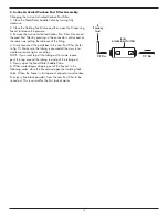
1. Check the tank precharge pressure.
Make sure it is between 5 to 7 psig
. If not, use a bicycle hand pump or other
pump to bring the pressure up to the 5 to 7 psig range.
2. Pull the cap/plug off the top of the tank where the Tank Shut–Off should go.
3. Wrap Teflon tape three times around the ¼" male outlet thread. Wrap in the direction of the threads (clockwise when
looking down on the Holding Tank). The tape will act as a thread sealant. Screw on the Holding Tank Shut–Off Valve.
4. Locate the
3
⁄
8
" Yellow Tubing. Firmly press one end into the Holding Tank Shut–Off Valve. The fittings will grab the tubing
and seal it in place. Make sure the tubing is pressed all the way in to create a pressure tight connection.
F. Start Up
1. Installing the pre filter, post filter, membrane module and sanitizing the holding tank.
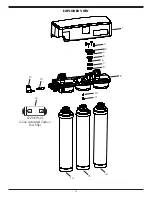
• Remove the plugs on the underside of the manifold labeled "SEDIMENT/CARBON". Unwrap the Sediment/Carbon
Modules (2), make certain the module has an O-ring on its stem and within the O-ring groove of the housing. With the
alignment notch facing manifold shut off (left), press module firmly into the manifold, tighten the modules ¼ turn to the
right by hand and turn into its locked position.
• Remove the plug labeled "Membrane" from the underside of the manifold. Unwrap the Membrane Module, make certain
the module has O-ring on its stem and within the O-ring groove of the housing. With the alignment notch facing manifold
shut off (left) press module firmly into the manifold, tighten the modules ¼ turn to the right by hand and turn into its locked
position.
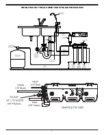
• Disconnect the yellow product water tubing that runs from the Holding Tank to the Manifold (see plate top view, page 5).
Put 50 drops of bleach (this is ½ tsp. or 3 ml) into the tubing and reconnect to the manifold plate.
2. Start rinsing the system:
• Slowly open the Feed Water Saddle Valve counterclockwise to its fully open position.
• Open the faucet to allow air to escape while system is filling the housings and tubing.
• Check the Air Gap Window on the Dispensing Faucet to be sure that the drain water is flowing.
• RO should be filling and purging air, when water starts dripping consistently from faucet spout, close faucet handle.
• Do not re-open the Faucet for at least 3 to 4 hours, or when auto shutoff valve closes (no water to
drain)
• Do not use the first three full tanks of water, open faucet to drain tank empty.
SECTION V
• OPERATION & MAINTENANCE
A. Normal Operation
1. It is normal for the Total Dissolved Solids (TDS) in the water to be higher than normal during the first 3 to 5 gallons of
operation; this is due to the sanitizing solution and the new Post Filters. After this water is rinsed to drain, the removal rate
should stabilize at a value of greater than 75%.
2. RO systems produce drinking water at relatively slow rates; it can take up to 3 to 5 hours or more to fill the Holding
Tank. Normal operation is to let the Holding Tank fill with water and then draw water as needed. When the pressure in the
Holding Tank falls to a given pressure (as the water is being used) the Automatic Shut-Off Valve (ASO Valve) will start water
production and the system will refill the Holding Tank. When the Holding Tank is full and no water is being used, the ASO
Valve will automatically shut off the feed water to conserve water. The more water that is used (up to the capacity of the
system) the better the RO system will function. Other uses for the water are flowers, pets and rinsing glassware.
With each use it is recommended that you run the faucet for at least 3 seconds prior to using water, this is especially
important if the system has not been used daily. After periods of non-use, such as a week of vacation or longer, it is better to
empty the Holding Tank and allow the system to produce fresh water for use.
Summary of Contents for CWQC50
Page 1: ...INSTALLATION OPERATION AND SERVICE MANUAL RO DRINKING WATER SYSTEM MODEL CWQC50...
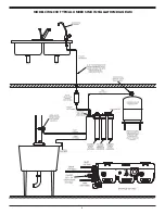
Page 5: ...5 MODEL CWQC50 TYPICAL UNDER SINK INSTALLATION DIAGRAM...
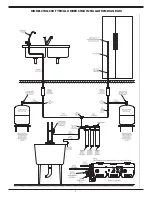
Page 6: ...6 MODEL CWQC50 TYPICAL UNDER SINK INSTALLATION DIAGRAM...
Page 7: ...7 MODEL CWQC50 TYPICAL UNDER SINK INSTALLATION DIAGRAM...


