background image


LiPo & LiFe, LiTo Battery Management System        BMS24T V4.0


www.chargery.com


page 19  total 41


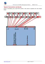
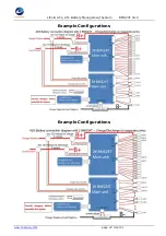
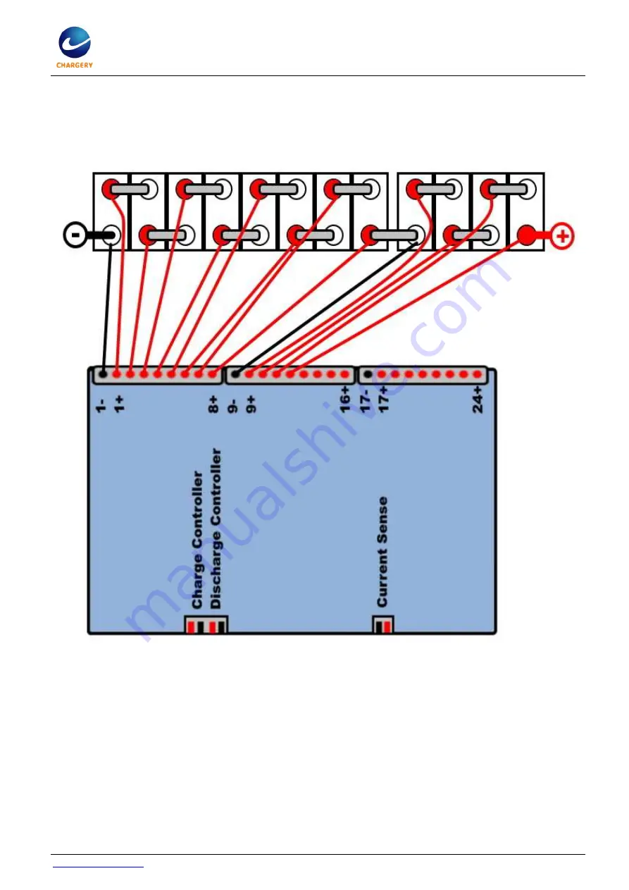
Typical Connection continued,


For  8S  /  12S  battery  pack,  connect  8S  to  socket  1,  then  socket  2  separately.  See  12S  example 

below:


.. 


Summary of Contents for BMS24T Series

Page 1: ...connecting any power sources battery or external to the BMS24T It is suggested that you view the BMS installation video from http www chargery com Video BMS24T_C10325_operation_instructions mp4 or htt...

Page 2: ...e color change or distortion 6 Do not try to charge non rechargeable dry cells 7 Do not mix batteries of different types different capacities or from different manufacturers all cells used should be o...

Page 3: ...ell balancing 7 Add low temperature protection on LCD unit V3 03 8 Optimized SOC accuracy New approaches are based on voltage and coulomb counting that take the individual cell impedances into conside...

Page 4: ...ter powering on the BMS24T and finishing setting up all of the parameters using the Display Module The BMS24T will use those settings even if the Display Module is disconnected from the Main Unit This...

Page 5: ...design the unit can be powered by all the cells or an external power supply 10 Detect cell count at any time and compare with the count detected when switched on first time If inconsistent the device...

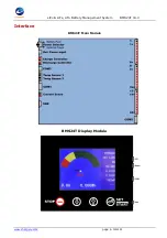
Page 6: ...LiPo LiFe LiTo Battery Management System BMS24T V4 0 www chargery com page 6 total 41 Interface BMS24T Main Module BMS24T Display Module...

Page 7: ...n unit to display module by gray spring wire COM3 Output RS232 level on the port any external device can read out all data from BMS24T Temperature sensor Two temperature sensors monitor the battery te...

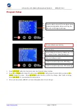
Page 8: ...rm the change After finish all setup press SET START for 3 seconds quit the setup menu 3 When quit setup mode BMS24T will record all parameters till next change Setup the High Temp Cut Off to the high...

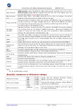
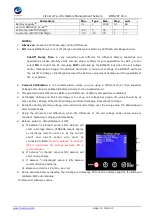
Page 9: ...gauge 5 20 90 1 Temperature Protection High Temperature cut off 30 50 80 1 Difference Diff of battery Temperature Temp 5 10 30 1 Voltage balance Protection Difference Diff of cell voltage 5 30 300 1 m...

Page 10: ...efore delivery for the supplied shunt 4 Temperature Alarm OFF means Battery and Difference of battery Temperature is disabled 5 Cell Empty Voltage and Cell Full Voltage is to set up cell voltage bar g...

Page 11: ...battery capacity and the more cell difference voltage there is the balancing time will be longer The battery discharge platform voltage is storage voltage so when the average cell voltage is just cel...

Page 12: ...d press SET START until the selection blinks then press DOWN UP button to modify finally press SET START button to run the BMS24T or wait for 8 seconds start automatically After started battery type a...

Page 13: ...the cell voltage and HIGH will be displayed in turn 11 When any warning events are triggered Press UP or DOWN you can check which cell triggered the warning events over charge or over discharge the v...

Page 14: ...13 100V 3A 5 Balance current 1 2A per cell 6 Temperature display range 20 150 7 SOC indicator RED area 0 15 of SOC YELLOW area 16 35 of SOC GREEN area 36 100 of SOC 8 Main module Size 128 114 33 L W T...

Page 15: ...tual maximum charge discharge current your system will use A single shunt is used for the BMS24T 75mV or less is recommended The BMS24T detects the charge and discharge currents using the same shunt A...

Page 16: ...make current blink and increase the current to the new value up to 125A it must be less than current shunt it is better to make it equal to your charging current the key is the current must be accura...

Page 17: ...lly 2 Connect PC to BMS with provided USB data cable and power on BMS if update Main Unit the LCD Display Module need not be connect to Main Unit NOTE BMS Main Unit and LCD Display Module must be upda...

Page 18: ...is for 2S 8S socket 2 for 9S 16S and socket 3 for 17 24S battery 1 2S 15S battery connected to the socket 1 and socket 2 directly but external power supply is required 2 For 15S or less configuration...

Page 19: ...LiFe LiTo Battery Management System BMS24T V4 0 www chargery com page 19 total 41 Typical Connection continued For 8S 12S battery pack connect 8S to socket 1 then socket 2 separately See 12S example b...

Page 20: ...LiPo LiFe LiTo Battery Management System BMS24T V4 0 www chargery com page 20 total 41 Typical Connection continued Typical 24S connection using all 3 sockets...

Page 21: ...LiPo LiFe LiTo Battery Management System BMS24T V4 0 www chargery com page 21 total 41 Typical Connection continued...

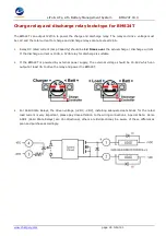
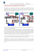
Page 22: ...wer the coil and the total current for charge and discharge relay s cannot be larger than 2 5A In this configuration the Charge Relay should be 1 25 times the maximum amperage provided by the charging...

Page 23: ...guration example This configuration requires that both Charge Discharge Relay s are capable of handling equal amperage Example 2000W 12V 166A X 1 25 208A 2000W 24V 83 3A X 1 25 105A NOTE Fuses DC Brea...

Page 24: ...ctual charge discharge current If the discharge current is 100A a 120A relay for discharge is suitable 2 If the BMS24T is powered by external power supply the external voltage should be 15 60V which c...

Page 25: ...f the Shunt as each separate BMS will read the current to and from that particular battery pack Remember that these relays must be sized at least 1 20 to 1 25 times the maximum anticipated Amperage th...

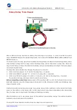
Page 26: ...lay time 2 seconds 3 Short circuit ONE of 3 jumpers J1 or J2 or J3 the delay time 6 seconds 4 Short circuit TWO of 3 jumpers J1 and J2 or J2 and J3 or J1 and J3 the delay time 3 seconds The small curr...

Page 27: ...ad being driven by the motor As the motor speed rises to its rated RPM Back EMF proportional to the RPM is generated in the winding s and the current draw reduces proportionately till it draws the run...

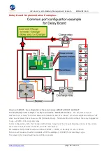
Page 28: ...Closed on when energized and Open off when de energized this is known as NO Normally Open Terminals 85 and 86 actuate the relay Suggested to use a 12VDC 10A or greater relay In this configuration bot...

Page 29: ...ay Suggested to use a 12VDC 10A or greater relay In this configuration the Discharge relay must be sized to the maximum Amperage anticipated x 1 25 For example 24V 4000W Inverter will draw 4000W 24VDC...

Page 30: ...LiPo LiFe LiTo Battery Management System BMS24T V4 0 www chargery com page 30 total 41 Example Configurations Example Configurations...

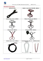
Page 31: ...hargery com page 31 total 41 Standard Accessory USB data cable Battery connection XHR 9PIN 600mm Temperature sensor 600mm Relay controller wire 600mm Warning LED 300mm Warning Beeper 300mm Current sen...

Page 32: ...V 20 12V 20 12V 20 12V 20 Close includes bounce Typ 10 ms 10 ms 10 ms 10 ms 10 ms Release includes arcing Max 40 ms 40 ms 40 ms 40 ms 40 ms Bounce after close only Max 3 ms 3 ms 3 ms 3 ms 3 ms Insulat...

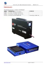
Page 33: ...Related parts The following device is related with BMS24T MODEL DESCRIPTION COMMENTS BMS16 For 2S 16S balance is not available BMS8T For 2S 8S 1 2A balance current per cell BMS16T For 2S 16S 1 2A bal...

Page 34: ...tage within safe values If using another brand of charger BMS24T only OPEN the Charge relay if the charge current is too high such as over 10A the relay will open and close repeatedly The relay life c...

Page 35: ...off balance in Discharge on or off Charge status charge current displayed over 1A Discharge status discharge current display under 1A such as 10A Storage status current displayed between 1A 1A So cur...

Page 36: ...rge 5 Charge or discharge current display is not stable or wrong a The wire length from current shunt to battery negative should be as short as possible b Check charge current or discharge current rip...

Page 37: ...tage d 12V 600A relay coil current is 1 3A at 12V drive voltage Because the relay coil current is far more than BMS working current to avoid any cell being over discharged please operate as below a if...

Page 38: ...ons are as below a Any cell voltage reaches Over discharge Protection P Voltage setting b The lowest cell voltage is under Over discharge Release R Voltage setting c Discharging current is over Over d...

Page 39: ...ed as well check the voltage at the terminals of the charger and note them as well You will now see a difference in readings between the Batteries the Solar Charge Controller the Inverter Charger This...

Page 40: ...work it shouldn t do The BMS of course will cut off for High Low Volt etc but this is not it s job those are safety features to protect you batteries and are more or less the fail safe mechanism as su...

Page 41: ...ng defect the accessory will be replaced or repaired Your Vendor Dealer is your first point of contact for warranty issues Return postage costs are the responsibility of the user in all cases Please s...

Reviews: