LiPo & LiFe, LiTo Battery Management System BMS24T V4.0
www.chargery.com
page 25 total 41
Solid State Relay supplemental information
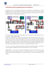
Because SSR's vary by manufacturer, carefully plan your configuration to accommodate your "specific
application" and how to best implement the relays for your needs. Bi-directional relays are the most
flexible and the least complicated to work with. Uni-directional relays can be used within a common-port
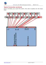
configuration as well. Simple examples shown below.
T
h
e
s
e
p
a
r
a
t
e
P
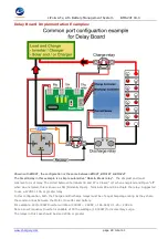
ort example shown, could also use a busbar between the Charge Relay and Charge Source if there is
more than one charge source available.
If more than one Battery Pack, each with their own BMS exists, the current sensing Shunt must be on the
battery side of the Shunt, as each separate BMS will read the current to and from that particular battery
pack. Remember that these relays must be sized at least 1.20 to 1.25 times the maximum anticipated
Amperage throughput that is expected. Relays capable f handling more amperage than expected will not
cause any issues. Example: If you know you will never exceed 100A Load Draw or Charge then you can
safely use 120A to 125A rated relays, you may chose to use 200A relays without concern.
If you wish to monitor the "complete battery bank" consisting of multiple battery packs, then a shunt will
be required between the NEG busbar and the actual Load such as an Inverter / Charger.
CAUTION NOTE: If your using a Common Port configuration, ensure that "both" relays are equally
matched, as the highest throughput current is the determining factor and if a relay is installed that
cannot handle the maximum Amperage that could pass through it, it will fail and possibly result in
damage.


