H-LINK Board (SPX-RAMHLK) Installation Manual
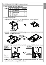
1. Check through H-LINK board accessories.
Table 1
No
Part Name
Quantity
1
3
1
1
H-LINK board
Board support
14 pin cord
Installation manual
2. H-LINK board installation
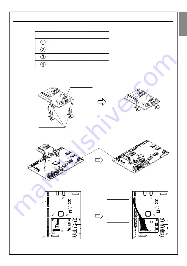
i. Assemble board support (3 pcs) to H-LINK board holes as following picture.
ii. Insert the H-LINK board into the MAIN board (please use 3 holes on MAIN board that
designed to fit the H-LINK board).
iii. Insert the 14 pin cord to the CN28 of the H-LINK board and CN1026 of the MAIN board.
H-LINK board
Board support
Connector
CN1026 of the
MAIN board
Connector
CN28 of the
H-LINK board
14 pin cord
iv. Set the SW1301 of the MAIN board to ON condition before start the H-LINK operation
(default position from factory is OFF condition).
SW1301 of the
MAIN board
MAIN board
ENGLISH


