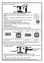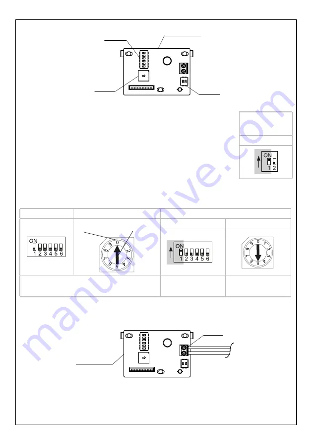
3. DIP switch setting.
H-LINK board
DSW1
DSW2
RSW1
i. DSW1 setting (terminal resistance setting).
Terminal resistance setting set by pin number 1 of DSW1.
(Default setting from factory is pin number 1 of DSW1 set to OFF
condition).
Terminal resistance should be ON in only one position in whole H-LINK.
After checking terminal resistance setting of whole H-LINK, pin number
1 of DSW1 should be set properly.
ii. DSW2 and RSW1 setting.
Refrigerant cycle number is set by DSW2 and RSW1.
DSW2 (tens digit)
RSW1 (ones digit)
Example: Setting cycle number to 15
Set it inserting a
screwdriver
Position
DSW2
RSW1
Default setting from factory for DSW2 and RSW1
are set to OFF and 0 respectively.
Pin number 1 is ON
The set position is 5
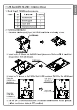
4. Connect the H-LINK board to the Central Station by fixing the transmision cable at CN29.
H-Link board
CN29
The transmission cable used shall be as below.
i. 2 cores cable (0.75mm
2
to 1.25mm
2
). Model : VCTF, VCT, CVV, MVVS, CVVS VVR, VVF.
ii. 2 cores twist pair cable. Model : KPEV, KPEV-S.
Total length of the transmission cable shall be below than 1000m.
Transmission cable
to Central Station
DSW1
Example:
If set pin number 1
to ON condition
Note: Indoor unit number will be addressed by outdoor unit automatically.


