030‐300377 Rev. A
Section LTCMPH-75-802
0316P4
Page 2 of 5
mounted inside the CMPH. Stake mounting is obtainable via molded channel
grooves, which are located at the center of each interior side wall of the base.
These grooves accept most new and existing enclosures’ mounting stakes.
1.5
Installation
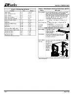
See Table 1 to perform a new CMPH enclosure installation. Table 2 de-
scribes a new CMPH installation with stakes, and Table 3 describes an
installation to replace an existing enclosure (rehabilitation installation).
- GROUNDING WARNINGS -
Always follow local codes and company practices for performing proper cable
and site bonding and grounding, and perform all bonding and grounding prior
to other electrical, fiber, and communications connections.
- CABLE DAMAGE WARNINGS -
Be careful not to damage any buried cables or service wires while digging either
to expose cables or to prepare a hole or trench, or while driving stakes.
Buffer tubes and fibers are sensitive to excessive bending, pulling, and crushing
forces. To avoid kinking of buffer tubes and fiber damage or breakage, exercise
great care when working with fiber, and do not exceed or violate minimum bend
radius requirements for fibers, buffer tubes, and cables.
- BODILY HARM WARNINGS -
Risk of serious eye damage! Never look into the end of a fiber optic line or circuit
nor use a magnifier in the presence of laser light or radiation. Always exercise
caution when installing, testing, or performing maintenance on live circuits. If eye
exposure to laser light or radiation has occurred or is suspected, immediately seek
medical treatment by a professional eye care physician.
Shards and cleaved glass fibers are very sharp and can easily pierce the skin. Do
not let cut pieces of fiber stick to your clothing or drop in the work area where they
can later cause injury. Use tweezers to pick up cut or broken pieces of glass fibers
and place them in a container specifically meant for this purpose.
The corrugated metal or armor that may be present in the feed cable is very sharp
at the cut or exposed edges. Extreme caution should be taken to prevent personal
injury. Protective work gloves are recommended when handling armored cable.
Cable and fiber cleaning solvents may contain hazardous materials or harmful
ingredients. Always read and follow the manufacturer’s precautions, warnings,
and instructions when working with cleaning solvents or products.
Table 1. Installing a New CMPH Enclosure
Step
#
Instruction
1.
h
Obtain tools, materials and equipment.
Gather the following equipment to
perform the CMPH installation.
h
216 tool or can wrench
h
Trenching and digging equipment and tools
h
Charles CMPH model
h
Cable grounding materials and tools
h
Scissors, knife or snips
h
Cable opening and management equipment
h
Level
h
Clean, dry, pea gravel
(3/8"‐5/8" diameter)
h
Measuring tape
h
Conduit and conduit caps
(optional)
h
Soil tamping tool(s)
h
Wrenches or socket set
h
Soil for backfill
h
Site cleanup tools
2.
h
Prepare trench.
Do not damage any buried cables or wires while
digging.
Dig and prepare the cable trench, per company practice.
3.
h
Place cables (or conduit or innerduct) in trench.
Follow company
practice to lay, place, and cut any cables and innerduct or conduit.
4.
h
Unpack and inspect equipment.
Remove the CMPH from its packaging.
Inspect the unit upon delivery; if damaged in transit, report the damage to the
shipping company.
5.
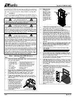
h
Disengage the CMPH lock.
Unlock the
CMPH using a 216 tool or can wrench
at the front hex nut‐in‐cup washer
screw; turn the cup‐washer screw
counterclockwise approximately 1/8
turn until it stops. Hold in this position,
then lift the dome up approximately 1"
(enough to disengage the self‐locking
latch) by grasping and lifting the
molded side rail.
Cup‐washer screw
inside dome self‐locking latch
216
Tool
6.
h
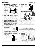
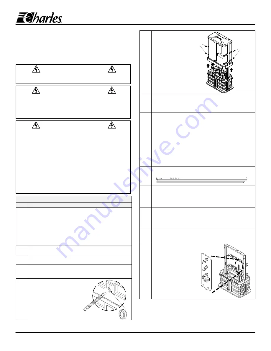
Remove the dome.
Set aside the can
wrench after slightly
lifting the dome, then
use both hands to
grasp a side rail (rib)
with each hand and
completely lift off the
dome from the base
.
Set aside the dome for
later use.
Pull up
on ribs
Pull up
on ribs
7.
h
Locate and remove red plastic bag
.
Remove the red bag labeled
“
moisture
barrier
"
included with the CMPH
.
Set it aside for later use.
8.
h
Optional - Replacement or rehabilitation mountings only.
For
applications to replace old enclosures, continue with the steps in Table 3.
9.
h
Determine and mark base installation location.
To determine exactly
where to place the base in the trench, use the base itself as a positioning
template by placing it up over the top of the conduit, innerduct, or cables
(route the cables through the base)
and lowering the base to the ground.
Analyze the site and position the base at its proposed final orientation and
horizontal positioning in the trench or hole and adjust accordingly. Mark this
proposed final spot by removing a shallow layer of top soil from around the
outside perimeter of the base about 2‐4 inches wider than the base. Set the
base aside.
10.
h
Dig a hole for the base.
Caution: Avoid damaging buried cables, wires,
innerduct, conduit or ground equipment whenever digging.
At and
within the marked perimeter boundary
,
dig
straight
down to a depth of 9
inches. Do not dig too deep.
11.
h
Stake mountings.
Refer to Table 2 for instructions to install mounting
stakes in Table 2.
12.
h
Put base in hole or trench and route cable(s) through base.
Route the
cables and conduit or innerduct up through the bottom of the base,
then put
the base in the prepared hole or trench.
Note: Ensure the base location allows technician access to the lock and any
equipment installed or to be installed in the CMPH.
13.
h
Verify proper base depth.
Before backfilling, verify the base is at the proper
depth, approximately 9 inches deep. Rest the base on solid or well‐tamped
soil when measuring this distance. Verify the base ground line indicator is at
the same level as the final‐grade ground line. Remove, add, or tamp more
soil as necessary.
14.
h
Level the base.
Verify that the base is level. Check the level in both
dimensions; front to back, and side to side. Make any needed base‐bottom
soil adjustments to bring the base to a level position.
15.
h
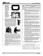
Prepare earth ground.
Always
follow local codes and company
practice when preparing earth
ground and when grounding
cables or equipment.
If an earth
ground is not present at the
CMPH site and local code or
practice requires an earth
ground, prepare one now. Attach
the earth ground to the CMPH's
ground lug on the ground plate
(Step 21) using a ground wire of
proper gauge, per company
practice.


