030‐300377 Rev. A
Section LTCMPH-75-802
0316P4
Page 3 of 5
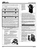
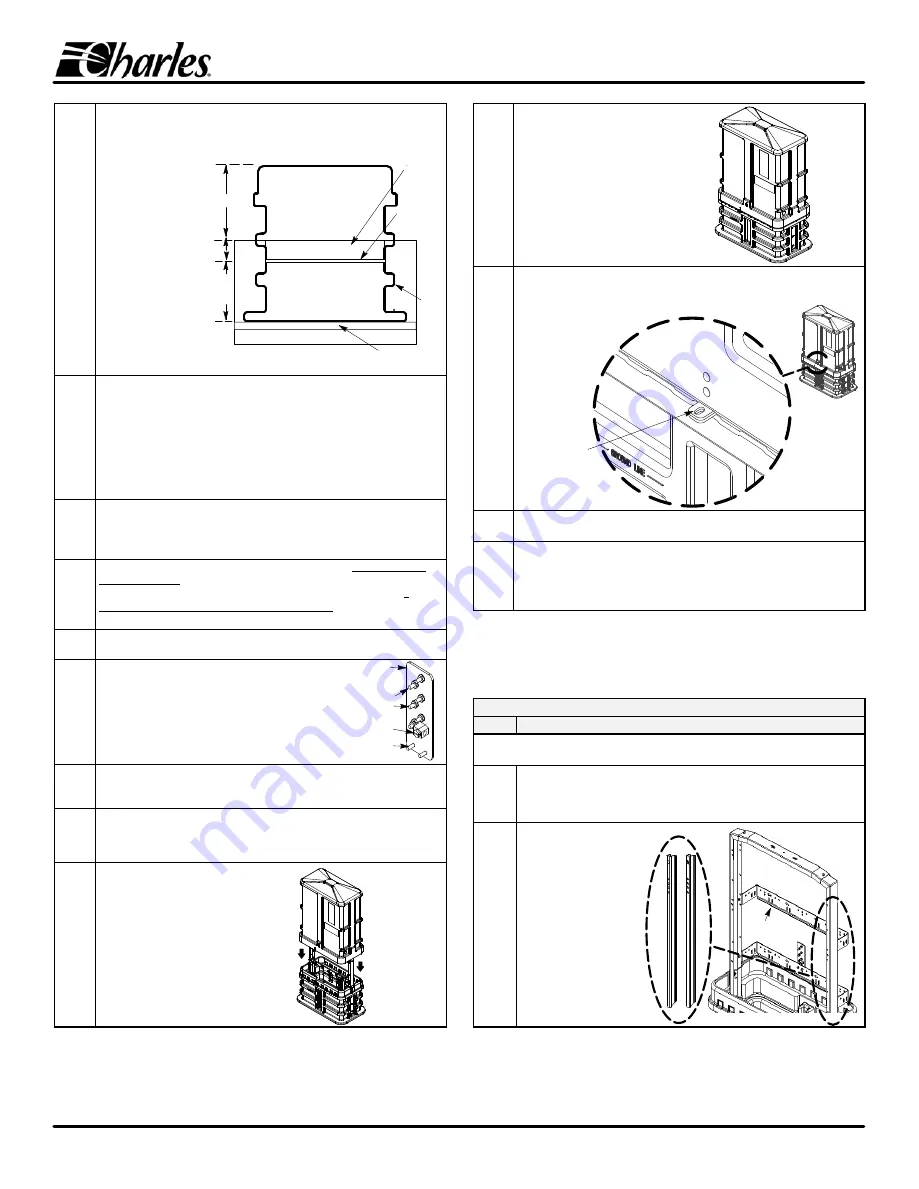
16.
h
Position the base on top
of the gravel and level the
base. Alternately backfill
the base on the inside
first then the outside,
tamping the soil as it is
added. This equalizes the
pressure inside/outside
the base and makes the
base more stable. The
backfill on the outside of
the base should be even
with the Ground Line on
the front of the base.
Inside, add backfill soil to
a point midway between
the first and second ribs.
2 to 3" gravel inside
the base (Step 18)
Base
Top
ÏÏÏÏÏÏÏÏÏ
ÏÏÏÏÏÏÏÏÏ
ÏÏÏÏÏÏÏÏÏ
ÏÏÏÏÏÏÏÏÏ
ÏÏÏÏÏÏÏÏÏ
ÎÎÎÎÎÎ
ÎÎÎÎÎÎ
ËËËËËË
Soil
Pea Gravel
Soil
Backfill and tamp inside/outside the base.
Once the hole has been dug to
the proper depth, a layer of pea rock /gravel must be placed at the bottom of
the hole.
Note: The base can be leveled more easily if it is placed on
gravel first.
8"
7"
Side View
Moisture
Barrier
(see
Step 17)
Base
Bottom
Ground
Line
2"
above
vapor
barrier
1st
Rib
of
Base
ÎÎÎÎÎÎÎÎÎ
ÎÎÎÎÎÎÎÎÎ
Gravel layer
17.
h
Place the red plastic moisture barrier.
The provided moisture barrier sheet
or bag must be placed on top of the tamped backfill soil inside the base. If it is
supplied as a bag, cut the sides so it can be spread over the backfill soil. Bring
it to the edges of the base so it covers as much of the backfill as possible. The
sheet can be cut to fit around any duct or cable entering the base, or an X can
be cut in the center to allow the sheet to be fitted over the cable or conduits.
The sheet serves to prevent excessive moisture from entering the CMPH.
Failure to use the plastic moisture barrier on top of the soil significantly
increases the risk of condensation inside the pedestal.
18.
h
Add gravel to the inside of the base.
Pour approximately 2 to 3 inches of
5/8", or smaller, pea rock or gravel into the base up to the second rib or 2
inches below any innerduct or conduit opening. Keep the duct openings
sealed when adding gravel. Spread out and level the gravel.
19.
h
End of base installation - determine next procedure.
If cable work will
now be performed, continue with the next steps and consult local practices
and equipment manufacturer instructions for the proper procedures. If
further cable work will NOT be performed at this time, skip to Step 24 to
close the CMPH enclosure.
20.
h
Perform cable routing and mounting.
Per company practice and local
codes
,
perform all cable routing, mounting, and management procedures.
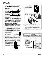
21.
h
Bond and strain‐relief the cables.
Ground or bond the cable(s) to the
ground posts provided on the ground
plate. Perform cable strain relief and
bonding per company practice.
Attach earth ground
to ground lug
Attach cable bond
straps to posts
Ground Plate
Posts to attach plate to ground bracket
22.
h
Finish cable work
&
equipment mounting.
Per company practice
,
perform
all cable opening
and splicing procedures
,
and equipment mountings and
connections
.
23.
h
Re‐check cable management.
Verify all equipment and cabling is organized
and will not contact the interior walls of the dome when installed (keep items
at least 1" from the vertical plane of the base collar). This assures safe and
smooth dome placement.
24.
h
Install dome.
Locate the dome and lift it
up and over the interior framework and
equipment. When replacing the dome,
make sure the lock side of the dome is
facing the catch side of the base. Lower
the dome until it overlaps and
self‐latches to the base.
Lower dome
onto base,
latch will
self‐lock
Align bottom of
dome with top
of base
25.
h
Verify the CMPH is locked.
The
dome design allows the dome to
self‐lock on the base. Verify the
dome is locked by attempting to
lift the dome.
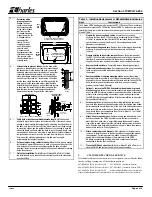
26.
h
(Optional) Padlock the CMPH.
For models equipped with an optional
hasp, the CMPH also can be locked by inserting a padlock through the
holes in the hasp provided at the front of the enclosure.
Hasp for padlock
(orderable option)
27.
h
Label outer dome.
Place all ID/warning labels on the dome, per company
practice.
28.
h
End of CMPH placement. Clean up site.
If no more equipment or cable
work will be performed at this time, clean up the site, fill and tamp any
trenches, replace any removed sod, restore the landscape to it's original
condition, pick up all equipment, and optionally leave this document inside
the CMPH for future reference.
Table 2. Installing the CMPH with New Charles Stakes
Step #
Instructions
Charles offers some CMPH models that include 2 mounting stakes (either 30", 36", or 42" long).
All stakes have identical hole patterns. This table describes how to install these models.
1.
h
Prepare the CMPH, trench, and cable.
Perform Steps 1‐10 of Table 1 to
open the enclosure and prepare the hole or trench and the cables or
conduit. Verify the base installation site is ready and suitable for metallic
stakes.
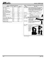
2.
h
Remove stakes from
CMPH framework.
Two
mounting stakes are
packed with the CMPH;
detach them from the base
lag bolts by removing the
nuts and washers which
secure them. Take care to
retain the hardware which
will be re‐used in
subsequent steps.
Remove but retain the nuts
that secure the stakes to
the inside of the enclosure
Fiber‐type bracket
(note offset depth)


