030‐300377 Rev. A
Section LTCMPH-75-802
0316P4
Page 4 of 5
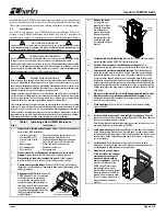
3.
h
Determine which
grooves to use for
stakes.
The base
contains a molded‐in
dual‐purpose groove
at the center of each
wall to accept the
U‐shaped mounting
stakes (as well as the
U‐shaped vertical
channels of the
frame). Per local
company practice
and site conditions,
select two wall
grooves that are
appropriate for stake
attachment purposes
(the grooves on the
shorter side walls are
typically used).
Base
Bottom
View
Open
Inside
Area
Alternate Mounting
Grooves
(generally used
in vault applications)
25.5"
29.5"
2"
1.5"
2"
17"
Base
Top
View
Preferred U-shaped channel
grooves for mounting stakes
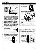
4.
h
1.6”
1.1”
Top View
of Stake
Set stake
into groove
Attach stakes to grooves in base.
Set the base on the
ground or a raised surface to access the grooves through
the base bottom. On the inside of the base, remove the
nuts and washers from the bolts (which are 4" apart) that
secure the frame channels in place. On the mounting
stake, the distance between the first and third hole down
from the top of the stake is 4". Insert the top of the stake
into the base, rotate the stake so it will fit properly into the
base groove (so the perimeters match), align the stake
holes with the bolts in the base, and set the stake in place
in the groove. Re‐install the lock washers and nuts that
were removed to secure both the mounting stake and
frame channel in place. Repeat for the other stake.
Base Side View
4
"
1
"
1.3
"
B
olt for frame channel and stakes
4
"
Charles
Stake
Top View of Base
Wall at Groove
1.125”
3”
1”
1”
1.2”
Carriage
Bolt
3
"
5.
h
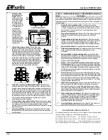
Verify hole or trench accommodates stake length.
Lift the base and
attempt to place it back in place in the trench or hole. If the trench is deep
enough to accommodate the length of stake protruding from the bottom of
the base, skip the rest of this step. If the hole or trench is not deep enough
to accept the stakes, and the weight of the base is not enough to drive the
stakes the length needed to allow the base to rest at its proper depth, then
once again use the base as a template to mark the exact stake locations in
the ground where more soil must be removed. Remove the base from the
hole, and at the stake‐hole indentations, dig down just enough to
accommodate the length of the stake.
6.
h
Set base in place, bring cables into base.
When the hole is deep enough
for the stakes, again lift the base by its walls or ribs and set it back into the
hole, being sure to enclose or encompass within the base all cables,
innerduct, conduit or equipment present at the site and intended for storage
inside the enclosure.
7.
h
Finish the installation.
Perform Steps 13 through 28 in Table 1 to finish
the installation. Be sure to backfill and firmly tamp soil
into the stake holes
when backfilling.
Table 3. Installing Replacement or Rehabilitation Enclosures
Step #
Instructions
The Charles CMPH has the same footprint as the UPC 1200 series. These instructions
describe how to replace a UPC 1200 with a Charles CMPH. To replace enclosures with
smaller footprints, remove the smaller enclosure and dig a wider hole, as described in
Step 9 of Table 1.
1.
h
Prepare the base, trench, and cables.
Locate the old or existing
enclosure (such as the UPC 1200 series) to be replaced. Perform Steps 1‐7
of Table 1 to prepare the new Charles CMPH enclosure, the hole or trench,
and the cables or conduit (skip Steps 2‐3 if trenching and new cable
placement is not required).
2.
h
Dig around existing enclosure.
Remove the dirt from around the existing
enclosure. Dig deep enough to allow the enclosure to be lifted and
removed.
3.
h
Prepare existing enclosure for removal.
Remove the bottom panels of
the UPC 1200. Locate the mounting stakes and remove the nuts and bolts
from them. Remove all attachments to the enclosure, including cable
supports and tie wraps, bonding connections, and grounding connections.
4.
h
Remove the old enclosure.
Completely remove the existing enclosure.
5.
h
Protect cables and connections.
Per company practice, wrap the existing
splice as tightly as possible without damaging the wire (or fiber)
connections.
6.
h
Analyze condition of existing mounting stakes.
Inspect the existing
mounting stakes for possible re‐use.
If
they are deteriorated, bent, out of
alignment, or have a hole pattern that will not work with the Charles CMPH
base, carefully remove the stakes and install new ones per company
practice (consult Table 2 if desired).
7.
h
Optional - remove the CMPH's horizontal splice bars and/or ground
bracket.
Analyze whether or not it will be necessary to temporarily remove
any of the CMPH's internal, horizontal, supportive splice bars or brackets in
order to fit the existing cabling, connections, splices, and equipment into
the CMPH during the base installation. After base installation, re‐attach the
bars and brackets (Step 10).
8.
h
Set base in place.
Lift the base over the existing cabling and equipment,
and route the wrapped splice and all equipment up through the base bottom
while lowering the base to the bottom of the hole. If the existing stakes were
used, verify they are
inside
the base. If new stakes were attached to the
base, insure the hole accommodates them
.
Perform Steps 13‐14 of Table 1
for the proper base depth and level
.
9.
h
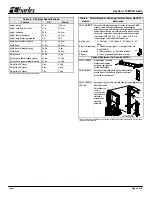
Attach base to re‐used stakes.
Remove the nuts and washers from the 4
bolts located inside the CMPH base that secure the frame channels in
place (2 bolts on each side, 4" apart). Manipulate the base and/or stake
tops so the re‐used stakes fit into the preformed stake grooves in the base
walls. Align the base bolts with the stake holes, and re‐attach the washers
and nuts onto the bolts. Firmly tighten nuts.
10.
h
Attach cables to bars and brackets.
If the splice bars or brackets were
removed, re‐install them now in the best positions to support (and ground)
the equipment. Per company practice, attach or mount all cables and
equipment to the internal framework (bars, brackets) of the CMPH.
Re‐attach any grounding, bonding, and cable connections previously
unattached to remove the old enclosure.
11.
h
Close the CMPH and clean the site.
Perform Steps 23 to 28 of Table 1 to
close the CMPH and restore the site to its previous condition.
2.
CUSTOMER TECHNICAL SERVICE
If technical assistance or customer service is required, contact Charles Indus-
tries by calling or using one of the following options:
847-806-8500 (Tech. Service local)
847-806-6300 (Customer Service)
800-607-8500 (Tech. Service toll-free) 847-806-6653 (Customer Service FAX)
847-806-8556 (Tech. Service FAX)
mktserv@charlesindustries.com (email)
techserv@charlesindustries.com (email) www.charlesindustries.com
(website)


