24
LT8019
•
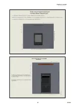
Position and fix the flue cover bracket centrally to the core drilled hole.
This will space the appliance 50mm from the rear wall or back panel.
•
Offer the appliance into position and mark through the gas pipe entry
hole (see connecting the gas supply section).
•
Pass a tape measure through the core-drilled hole and record the distance
from the inner and outer spigots to the surface of the outside wall.
Include the length of the spigots themselves in this measurement for the
engagement allowance.
•
Mark the outer pipe measuring from the terminal which will end up
nearest the wall. DO NOT cut right through at this stage, as the inner tube
needs to be LONGER than the outside one. Failure to do this correctly
could lead to scrapping of the flue tube and having to order another to
ensure safe operation. Cut the outer tube to length, ensuring it is cut
square and the edges are free from any rough edges.
•
Now measure from the same position for the inside pipe dimension and cut to length ensuring it is cut square and
the edges are free from any rough edges.
•
Apply flue seal or fire cement to the inside edges of both flue pipes and insert through the hole and onto the fire
spigots.
•
Drill the four fixing holes through the holes in the flange of the terminal and fix back using plug and screws.
•
If the flue outlet is fitted below 2m from the floor or a balcony level then the flue terminal guard must be fitted.
•
Complete the gas connection (see connecting the gas supply later in this manual).
INSTALLING THE APPLIANCE INTO DEEP REBATED FIRE SURROUND OR INGLENOOK CHIMNEY BREAST.
(When
installing in a timber framed dwelling reference must be made to the specific installation requirements stated later in
this
Section ‘Installing The Appliance In Timber Framed Dwelling’
)
.
•
Ensure there is a suitable outside wall constructed of non-combustible materials and that the flue position meets
the requirements previously described.
•
Mark a horizontal line on the wall at the intended hearth surface or appliance base height. If required the skirting
board must be cut away from behind the fire.
•
Mark a vertical line on the wall at the intended centre of the appliance up from the horizontal line for a height of
595mm.
•
Mark a short horizontal line so it crosses the centre line at 480 mm above hearth level line. This is the centre point
for the flue duct hole.
•
Using a long masonry drill, make a pilot hole completely through the wall. Ensure the hole is drilled accurately at
the centre and square to the wall both horizontally and vertically at the cross point previously marked.
•
Using 150mm (6”) core
drill cut the hole following the pilot hole. Drill from the outside of the dwelling through to
the cavity, and from the inside through to the cavity for best results.
•
Remove any combustible material that may be present if the rear of the appliance is contacting the wall i.e. ensure
no battens etc., behind dry lining in the area shown around the flue and top of firebox. Always remove a 25mm
(1”) area around the flue if plasterboard etc is present anyway.
•
Lay the base so that it is positioned correctly to the horizontal line.
•
Temporarily position and fix the back panel and deep surround, or construct a dummy chimneybreast as required,
using
NON-COMBUSTIBLE MATERIALS
ONLY
.
•
Offer the appliance into position and mark through the gas pipe entry hole (see connecting the gas supply section).
Flue cover bracket
Summary of Contents for Edge 3s BF
Page 15: ...www charltonandjenrick co uk 15 LT8019 Appliance Dimensions EDGE BF EDGE 3s BF ...
Page 21: ...www charltonandjenrick co uk 21 LT8019 ...
Page 22: ...22 LT8019 ...
Page 32: ...32 LT8019 SECTION FOURTEEN Wiring Diagram Maintenance Instructions ...
Page 34: ...34 LT8019 Register your appliance online today to active your warranty ...
Page 37: ...www charltonandjenrick co uk 37 LT8019 ...
Page 38: ...38 LT8019 ...


