background image


     Page 7 of 9 


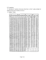
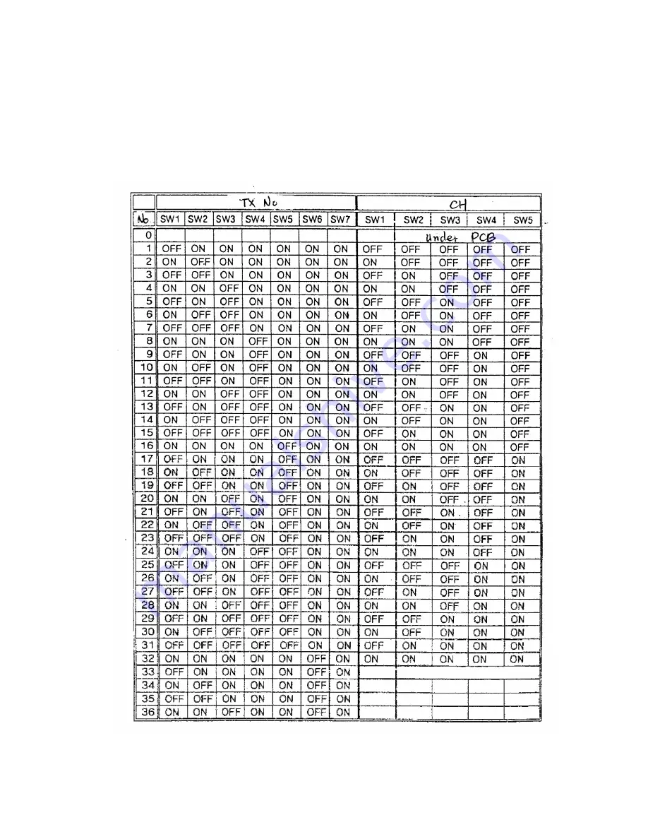
2)  Transmitter  

①  Switches for number choice are from No.1 to No.7, and switches for 

channel choice are from No.1 to No.5.  

② Number Choice  


Summary of Contents for Happy Call MC-6000 Series

Page 1: ...could void user s authority to operate the equipment This device complies with part 15 of the FCC Rules Operation is subject to the following two conditions 1 This device may not cause harmful interference and 2 This device must accept any interference received including interference that may cause undesired operation CHARMSORI Electric Telecom Co Ltd ...

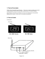
Page 2: ...ss calling system which adopted High performance CPU Central Processing Unit of Pro Chips Company Using Wireless Transmitter and Receiver User can communicate each other without talking by face to pace so this device is very useful at restaurants 2 Product Details 1 Receivers Front View Rear View ...

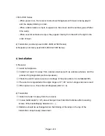
Page 3: ...eceiver MC 6000 Series When power is on the receiver conduct self diagnosis with music is being played and the display blinking in order When a table number is input it appears on the screen and the number goes off after time setup Input numbers can be memorized maximum 10 and replayed ...

Page 4: ... Avoid humid places Install it at least 3m away from wireless devices such as wireless phones and the places of big magnetism such as speakers Check the electric power source and voltage of the place where it is installed 220V The antenna is regulated at the angle ranges of 0 45 and a 3 stage antenna is used When power is on check the self diagnosis refer to 1 3 2 Transmitter Install it at least 3...

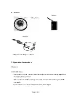
Page 5: ... by the only power connection without additional electric wire The channel choice of the translator is the same as the channel regulation of the backside receiver SW1 SW2 and SW3 are turned on always The translator should be installed in places near the regions where transmission is not available ...

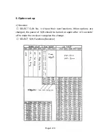
Page 6: ...set up 1 Receiver SELECT S W No 1 4 have their own functions When options are changed the power of S W should be turned on again after 4 5 seconds off to make the receiver recognize the change SELECT S W Functions Receiver ...

Page 7: ...Page 7 of 9 2 Transmitter Switches for number choice are from No 1 to No 7 and switches for channel choice are from No 1 to No 5 Number Choice ...

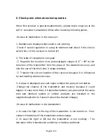
Page 8: ...he use of the thick side 3 stage antenna Transfer the current location of the receiver because it is influenced by surrounding wireless devices 3 A place is displayed as a call region without the press of call button Change the channel of the transmitter and receiver because it could happen in case more than 2 transmitter buttons are pressed at the same time and identical system or similar product...

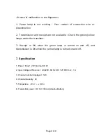
Page 9: ...een yellow lamps under the translator 3 Receipt is OK when the green lamp is turned on and off and transmission is OK when the yellow lamp is turned on and off 7 Specification 1 Power Max 1 2 W Normal 0 8 W 2 Input Voltage of Receiver AC220V 60 Hz DC 12V 850 mA 1 A 3 Channel number displayed 128 4 Channel Quantity 32 5 Temperture 10 60 6 Transmitter power DC 12V 33 mA Alkaline Battery ...

Reviews: