Using the Indexing System
The lathe is fitted with an indexing system which allows the spindle to be locked in any of 36 positions (i.e.
at 10 degree intervals). The indexing facility is useful for fluted columns, clock faces and accurate hole
placements.
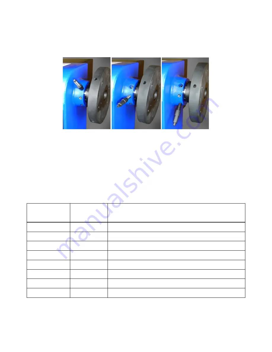
Pin Position A Pin Position B Pin Position C
There are three holes in the headstock casting which will accept the Indexing Pin. These are 20 degrees
apart. The spindle has twelve holes 30 degrees apart and a combination of these will enable you to mark
your workpiece for evenly spaced features.
Pin Position A is unthreaded and will accept the unthreaded end of the Indexing Pin. This position can be
also used to lock the spindle when removing chucks, faceplates etc.
Pin positions B & C are threaded and are used in combination with the threaded end of the Indexing Pin
NUMBER OF
SEGMENTS
ANGULAR
SPACING
DEGREES
PIN PLACING/SPINDLE HOLE COMBINATION
2
180
A1, A7
3
120
A1, A5, A9
4
90
A1, A4, A7, A10
6
60
A1, A3, A5, A7, A9, A11
9
40
A1, A5, A9, B3, B7, B11, C1, C5, C9
12
30
A1, A2, A3, A4, A5, A6, A7, A8, A9, A10, A11, A12
18
20
A1, A3, A5, A7, A9, A11, B1, B3, B5, B7, B9, B11, C1, C3, C5, C7, C9, C11
36
10
A1-12, B1-12, C1-12
Summary of Contents for 1624V
Page 18: ...Charnwood 1624V Parts Drawing ...


