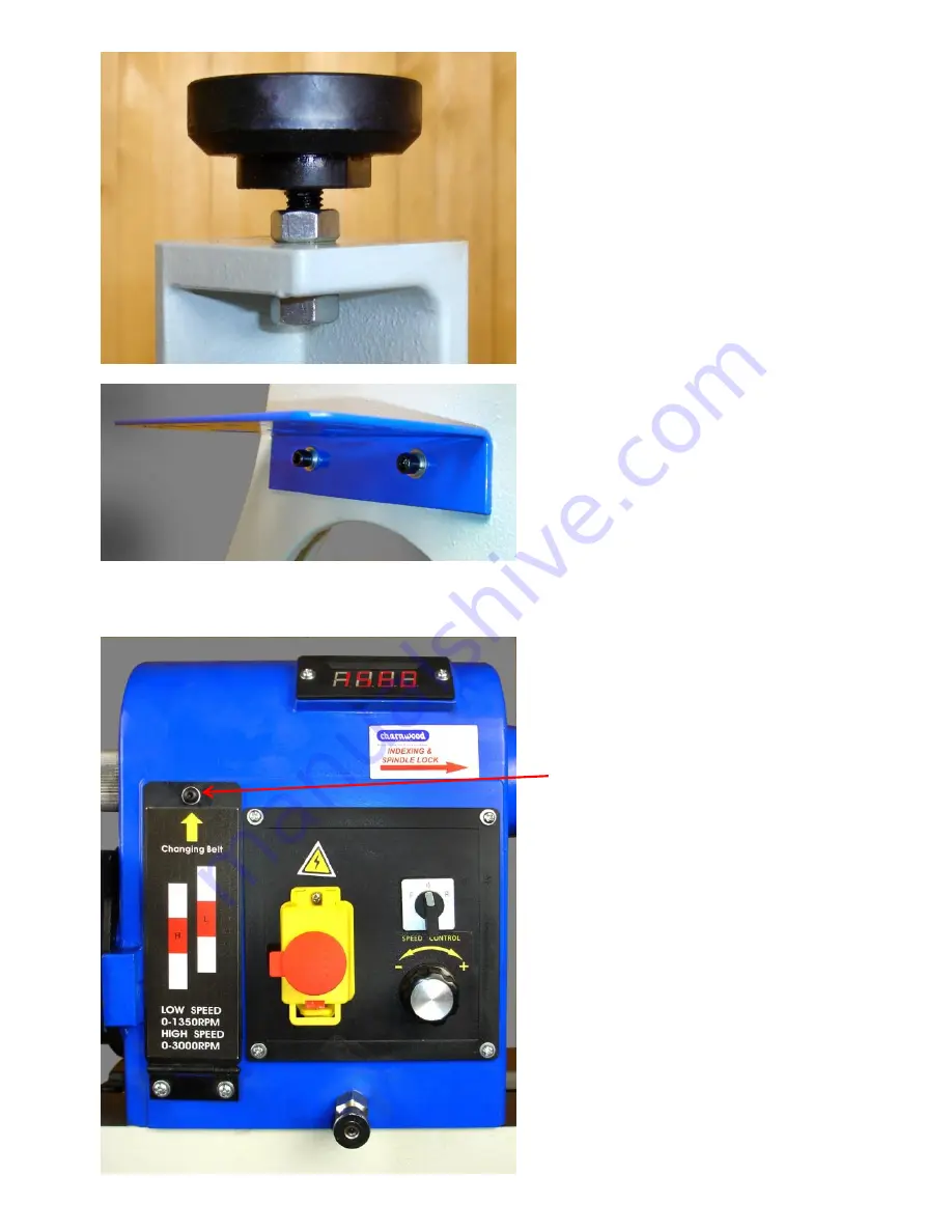
Attach one foot to each of the legs.
These can be adjusted to level the lathe bed
when it is in its final position.
Invert the bed/leg assembly.
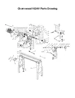
Attach the Tool Rack to the left hand leg with
two M8 x 16mm bolts, flat & spring washers.
Refit the headstock, toolrest and tailstock
assemblies to the lathe bed.
The headstock is fitted at the tool rack end of
the bed.
Replace the two end stops.
Adjusting the Spindle Speed
The lathe has electronic speed control.
There are two ranges of speeds which
are obtained by changing the position of
the drive belt.
To adjust the drive belt position:
1) Open the belt/pulley access door by
unscrewing the securing screw with the
3mm hex key. (this screw can be
replaced by the knurled head screw
supplied but only if the lathe is being used
in a non-European Union country)
Summary of Contents for 1624V
Page 18: ...Charnwood 1624V Parts Drawing ...


