®
INSTALLATION INSTRUCTIONS
charnwood
BAY
The air supply inlet can be fitted in the room or outside, in
accordance with the requirements in 'Air Supply' section (p11). The
inlet grille must not constrict the airflow through the duct and it must
be permanently open. A semi rigid aluminium flexible duct of no less
than 100mm diameter is used to bring the air to the stove . The duct
must be less than 5.5m long, have no more than five 90
º
bends and
two 45
º
elbows. The duct should be terminated with a jubilee clip
around the spigot provided and positioned conveniently for
attachment to the convection casing.
CONNECTING THE FANS
The adaptor provided must be connected to a suitable mains socket.
For the UK adaptor this is a 240 volt 50 Hz. a.c. supply. For the
European adaptor this is a 220 volt 50 Hz. a.c. supply. THE MAINS
ADAPTOR MUST BE USED. DO NOT CONNECT A MAINS
SUPPLY DIRECTLY TO THE STOVE.
Plug the connector from the adaptor into the socket on the wire from
the stove. Cable clips or conduit may be used to retain the wire if
desired. If it is necessary to extend the wire then ensure that the
correct polarity is maintained. The centre pin on the plug must be
positive. There is a thermal cut out linked into the fan control. This
means that the fans will not operate until the stove warms up.
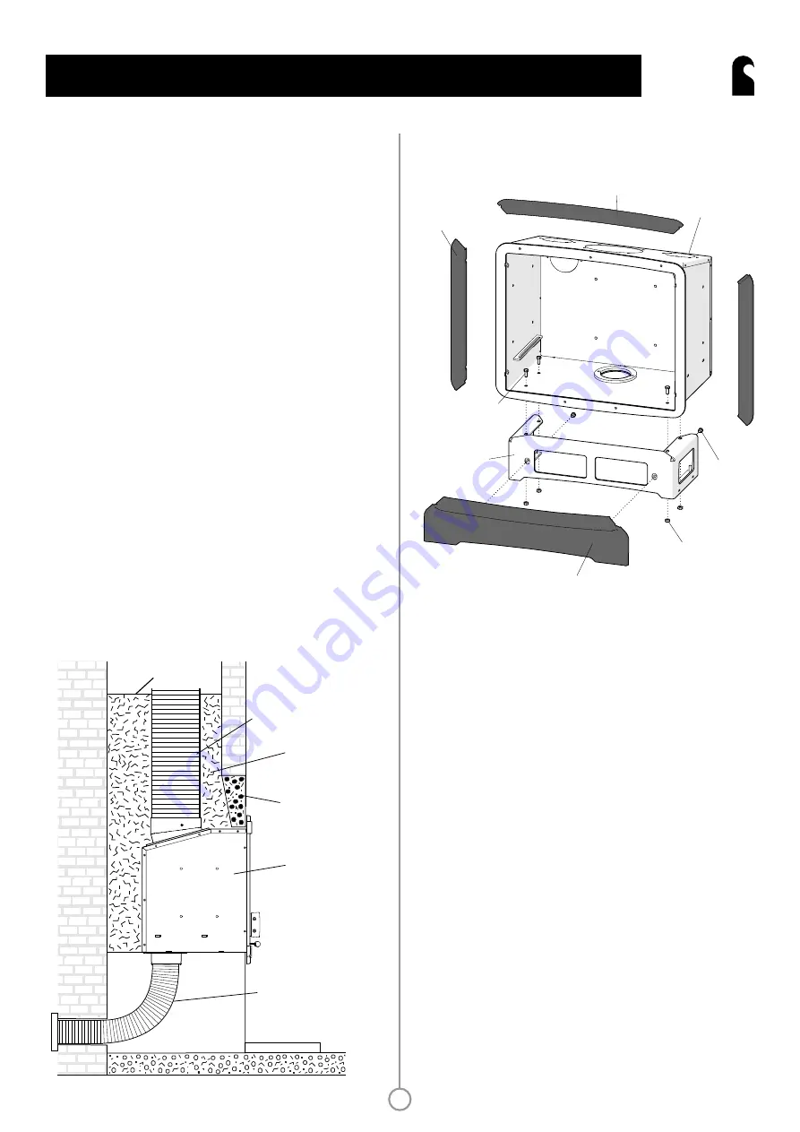
Fig. 12 Installation in a standard chimney
Lintel
Flexible flue liner
Closure plate
Stove
External air kit
to outside wall
Vermiculite infill
Pour down from
top of chimney
13
FITTING THE OPTIONAL BASE ASSEMBLY
1. With the firebox removed, roll the outer convection casing onto its
back and fasten the assembly into position using four M6x20 screws
and nuts. Insert the screws through the holes in the underside of the
casing from the inside and fit the nuts onto the outside of the base.
Do not fully tighten the screws at this stage.
2. Attach the lower fireplace trim into position onto the base frame.
This part replaces the lower trim piece (002/MR113). Use two
M8x10 screws and finger tighten them to allow adjustment.
3. Undo the foot adjustment screws on the base assembly so that
they are just below the lower level of the base frame. Stand the
whole assembly up onto the base and trial fit into the fireplace
opening. Adjust the feet to overcome and rocking, should the
fireplace floor be uneven.
4. Trial fit the side trim pieces (002/XR112 or 002/MR112) and
adjust the lower fireplace trim position to obtain a good fit. Once
everything is aligned, tighten all fasteners.
Lower fireplace trim
Base
Assembly
M8 Nut
Side Trim Piece
Convection Casing
M8x10
Screws
M8x20 Screws
Top Trim Piece
Fig. 13 Fitting the optional base assembly
Summary of Contents for 5
Page 1: ...Operating Installation Instructions charnwood BAY 5 5GT ...
Page 2: ......
Page 23: ......


