background image

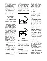
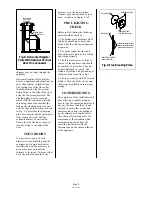
The hot water system should be a
gravity circuit and must be correctly
vented as shown in Fig. 4.

The steel boiler together with a
double feed indirect hot water storage
cylinder to BS:1566 part 1 should be
used in most situations, unless the
appliance is to be fitted in a soft
water area in which case the stainless
steel boiler may be used with a direct
hot water cylinder.

All pipework in the primary circuit
must be 28mm diameter and the flow
pipe must rise continuously from the
boiler to the open vent.

If an indirect cylinder is used then
the primary circuit should be filled
with a suitable inhibitor to prevent
the build up of scale and corrosion.

FITTING THE

OPTIONAL ADD-IN

BOILER

The boiler replaces the rear firebrick.
On the Country 8 the boiler also
replaces the throat plate, on the
Country 12 a special throat plate,
(part no. 010/BV35), is required.

Before fitting the boiler, remove the
front firebars, the side and back fire
plates, the throat plate and the rear

firebrick. Knock out the knock-outs
for the boiler tappings in the back of
the firebox.

Remove the backnuts and fibre
washers from the boiler tappings and
fit the boiler into the appliance. Place
the fibre washers over the tappings
on the outside of the appliance and fit
the backnuts, ensuring that the boiler
is held tightly against the rear inside
face of the appliance and that the top
edge of the boiler is level or runs
uphill to the flow tapping.

Gaps between the boiler and the
firebricks should be filled with fire
cement. Replace the back fireplate,
the side fireplates and the front
firebar. On the Country 12, fit the
new throat plate.

Connect the boiler to the heating
system ensuring that the flow pipe
rises from the boiler. Fill the system
with water and check for leaks.
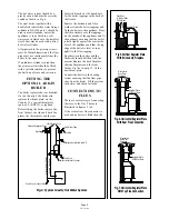
CONNECTIONS TO

FLUES

There are several ways of connecting
the stove to the flue. These are
illustrated in figures 5 to 8.

If the vertical rear flue connector is
used and no boiler is fitted then the

Soot Door

in Side or Rear

Of Chimney

Register Plate

With Soot Door

Soot Door

Alternative

Positions

Register Plate

Soot Door

With Soot Door

Alternative
Positions

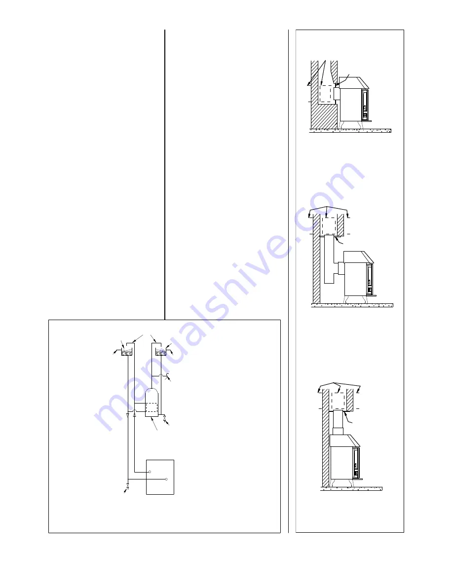
Fig. 7. Horizontal Register Plate

With Top Flue Connection

Fig. 6. Horizontal Register Plate

With Rear Flue Connection

Fig 5. Vertical Register Plate

With Bricked Up Fireplace

Register Plate

Fig. 4. Typical Gravity Hot Water System

Drain Cock at Lowest Point

Drain Cock

Gravity Return 28mm

Gravity Flow 28mm

Indirect Hot Water Cylinder

Cold Water Tank

22mm Open Vents

Overflow

Domestic Hot Water Draw Off

Overflow

Feed and Expansion Tank

Page 8

TW16 3/99

Summary of Contents for Country 12 Mk2

Page 1: ...on Instructions CHARNWOOD Country 8 MkII and Country 12 MkII Flat Top Low Canopy High Canopy Multifuel Roomheaters Bishops Way Newport Isle of Wight PO30 5WS U K Tel 01983 537799 Fax 01983 537788 E Mail charnwood ajwells co uk ...

Page 2: ... Trouble Shooting 6 Installation Instructions Health Safety Precautions 7 Performance 7 Chimney 7 Hearth and Fire Surround 7 Hot Water System 7 Fitting The Optional Add In Boiler 8 Connections To Flues 8 Soot Doors 9 Pre Lighting Check 9 Commissioning 9 Overall Dimensions Country 8 10 Overall Dimensions Country 12 11 CHARNWOOD COUNTRY 8 Mk II COUNTRY 12 Mk II Operating and Installation Instruction...

Page 3: ...son in a well ventilated dry place for at least one year but preferably two years before use Peat Ensure that the peat is well dried before use Burning wet peat will give rise to heavy tar deposits and reduced outputs PETROLEUM COKE IS NOT SUITABLE FOR USE ON THIS APPLIANCE ITS USE WILL INVALIDATE THE GUARANTEE At first you may find it helpful to try several fuels to find the most suitable If you ...

Page 4: ...ning wood or peat ash should be allowed to build up and generally weekly riddling will be sufficient The fire should be riddled with the doors shut see Fig 2 Place the tool onto the riddling lever and rotate between the 1 o clock and 3 o clock positions several times Too much riddling can result in emptying unburnt fuel into the ashpan and should therefore be avoided If any clinker forms it should...

Page 5: ...t use abrasive cleaners or pads as these can scratch the surface which will weaken the glass and cause premature failure Aerosol spray cleaners should not be used near the appliance whilst it is under fire When not in use If the fire is going to be out of use for a long period for instance in the summer then to prevent condensa tion and hence corrosion the thermostat should be left at the maximum ...

Page 6: ...hanging the front firebars will cause the glass to blacken It is always more difficult to keep the glass clean when running the stove very slowly for long periods If blackening of the glass still occurs check that the top of the stove is bolted on securely and that the seal between the top and the body is intact Also check that all flue connections and the blanking plate are well sealed It is also...

Page 7: ...sought regarding the necessity of having the chimney lined If it is found necessary to line the chimney then a lining suitable for Solid Fuel must be used If there is no existing chimney then a prefabricated block chimney or a twin walled insulated stainless steel flue to BS 4543 can be used either internally or externally These chimneys must be fitted in accordance with the manufacturers instruct...

Page 8: ...hers over the tappings on the outside of the appliance and fit the backnuts ensuring that the boiler is held tightly against the rear inside face of the appliance and that the top edge of the boiler is level or runs uphill to the flow tapping Gaps between the boiler and the firebricks should be filled with fire cement Replace the back fireplate the side fireplates and the front firebar On the Coun...

Page 9: ...ust all be fitted and should move freely and easily when the riddling mechanism is operated 2 The plates round the sides and back of the grate must be in position and sitting correctly 3 The throat plate must be fitted in the roof of the appliance and should be checked to ensure that it has not become dislodged in transit The method of location and positioning of the throat plate is shown in fig 3...

Page 10: ...High Canopy Country 8 LC Low Canopy Country 8 FT Flat Top 552 508 381 1012 526 526 526 381 752 552 513 322 513 381 513 513 322 513 322 639 513 460 1072 106 587 812 126 699 587 587 46 469 46 461 125 Country 8 MkII Dimensions All dimensions are in mm Page 10 TW16 3 99 ...

Page 11: ...0 180 210 180 210 655 1098 320 462 386 518 1158 584 106 45 655 793 320 Ø154 462 386 518 853 584 125 489 45 658 595 320 Ø154 462 386 518 718 584 125 468 45 Ø154 616 480 Country 12 HC High Canopy Country 12 LC Low Canopy Country 12 FT Flat Top Page 11 TW16 3 99 ...

Reviews: