

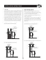
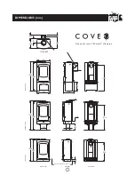
that the hearth must extend in front of the stove by at least 300mm
(12 inches) and to the sides of the stove by at least 150mm (6
inches). When the fire door is open, it extends beyond the front of
the stove by:
390mm (15.3in) 414mm (16.3in) 491mm (19.3in)
If in doubt as to the positioning of the stove expert advice should be
sought either from the supplier or the local building inspector.
If the vertical rear flue connector (shown in Fig. 9) is used then the
chimney may be swept through the appliance.
Horizontal lengths of flue must be kept to a minimum and should not
be more than 150mm (6 inches) long. The sealing face of the flue
collar should be coated with fire cement before fixing to the body of
the stove using the two screws provided. The blanking plate must be
removed, sealed with fire cement and refitted, care being taken to
ensure that the fold on the clamping plate is in line with the lugs on
the firebox as shown on the label on the clamping plate. Ensure that
the clamping plate does not prevent the throat plate from seating
correctly. All flue connections must be well sealed.
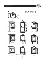
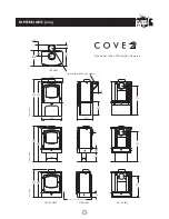
COVE 1 COVE 2 COVE 3
The fireplace must allow good circulation of air around the appliance
to ensure that maximum heat is transferred to the room and also to
prevent the fireplace from overheating. A gap of 150mm (6 inches)
each side and 300mm (12 inches) above the appliance should give
sufficient air circulation. If a wooden mantelpiece or beam is used in
the fireplace it should be a minimum of 460mm (18 inches), and
preferably 600mm (24 inches) from the appliance. In some situations
it may be necessary to shield the beam or mantelpiece to protect it.
In order for the fire to operate correctly there must be an air gap
behind the appliance of at least 40mm, but be aware that this
distance will need to be greater in some cases to meet Building
Regulation requirements.
There are several ways of connecting the stove to the flue. These are
illustrated in figures 6 to 9.
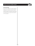
It is possible to pass a 16 inch diameter sweeps brush through the
appliance but in most back outlet installations it will be necessary to
have a soot door to enable the chimney to be swept. This may either
be in the actual brickwork of the chimney or in the register plate.
Various types and positions of soot doors are shown in figures 6 to 9.
CONNECTIONS TO FLUES
SOOT DOORS
UNPACKING THE STOVE
The stove arrives bolted and shrink-wrapped to its pallet. The
wrapping is first removed, then the stove released from the pallet by
removing the 4 pallet bolts using a 10mm spanner. The pallet brackets
can now be removed from the stove by tilting it and using a 13mm
spanner to remove the bolts. These 4 bolts are required for levelling
on the Low Stand or fixing on the Centre Stand, but are not used on
the Store Stand. The Stove comes with the Low Stand fitted and if
this is to be used, the Stove may now be moved to its final position.
The pallet is intended to be cut up and used for kindling fuel.
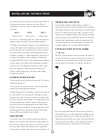
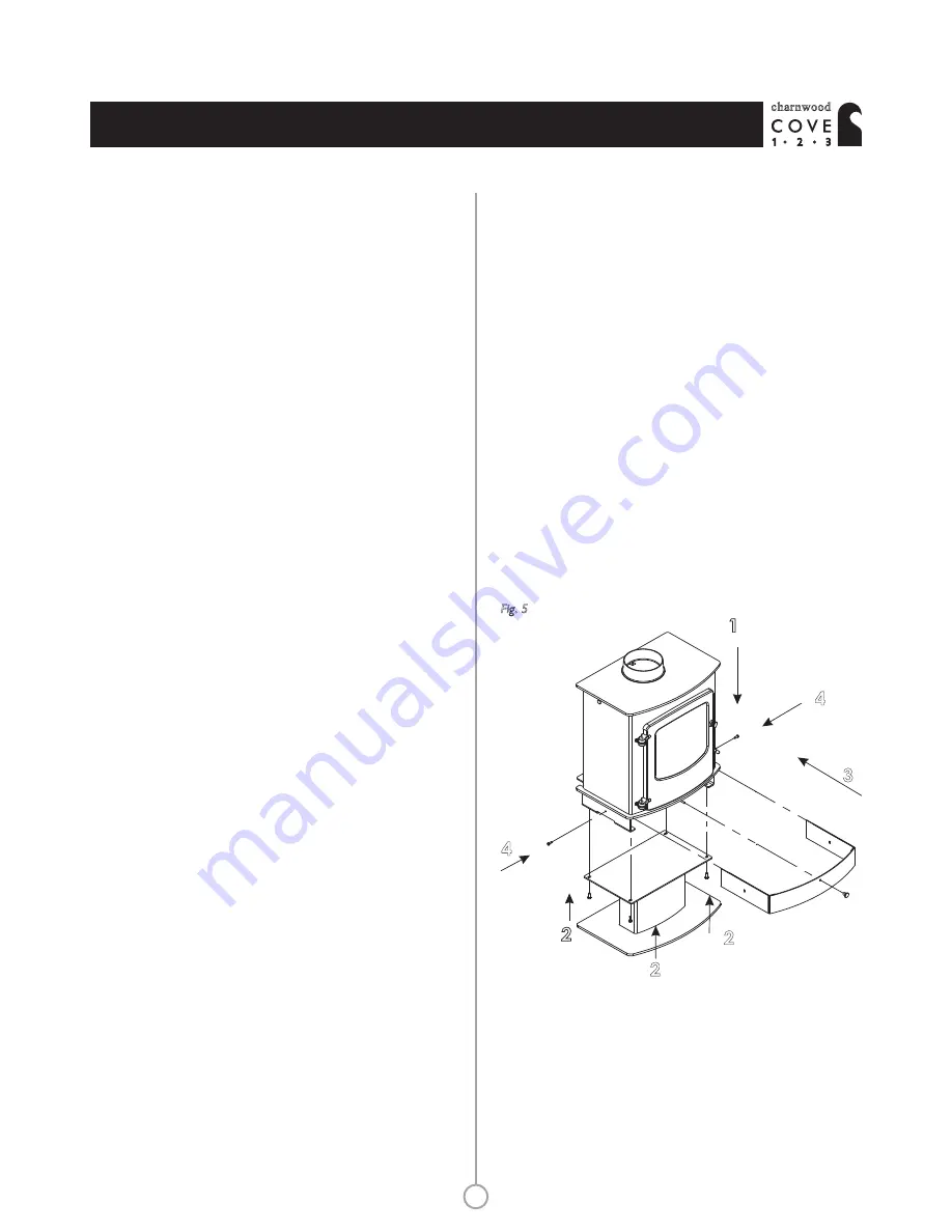
FITTING THE STOVE TO ITS STAND
1. Centre stand
The Stand is first positioned on the hearth in the desired position of
the stove. The lower cover must be removed from the stove by first
unscrewing the air control knob, then removing the 6mm bolt on
each side using a 10mm spanner. The Cover may now slide off.
Ensure that the pallet brackets have been removed from the stove,
then lift the stove on to the stand, aligning the 4 tapped holes in the
base brackets with the 4 slots in the top of the stand. NOTE: This
requires at least 2 people. The stove is fixed to its stand using 4 M8 x
20mm bolts and 4 plain washers. A 13mm open ended spanner is
required. Replace the cover, side bolts and Air Control Knob.
1
2
Fig. 5
2
2
3
4
4
®
charnwood
INSTALLATION INSTRUCTIONS
10
Summary of Contents for Cove 1
Page 1: ...Operating Installation Instructions charnwood 1 2 3 ...
Page 2: ......


