background image


R-NET 

www.chasswheel.com  

rev. 1 

2014-05-08


28


WEEKLY INSPECTIONS


Brake tests are made on an even floor, with at least one meter of free space around the wheelchair. 

Switch on the control system. Check that the light bar is lit in one second or flashes slowly. Push the 

joystick  slowly  forwards  until  you  hear  the  parking  brakes  working.  The  wheelchair  may  start 

moving. Release the joystick immediately, and you should be able to hear the sound of the brakes 

operating in a few seconds. Repeat this test three times also by pushing the joystick backwards, and 

to the left and right. 


Check the operation of the lights, turn indicators and the balance adjustment. If the wheelchair has 

an electrically adjustable back and/or foot rest, also check their operation. In problem situations, do 

not use the wheelchair, but contact service. 

 
CLEANING AND DISINFECTION THE WHEELCHAIR 


Clean the wheelchair with a moist soft fabric and diluted cleaning fluid. Avoid the use of undiluted 

cleaning  fluids  as  these  may  damage  the  plastic  and  fabric  parts  of  the  wheelchair.  Follow  the 

recommendations set by  the  cleaning fluid manufacturers regarding  the different materials. In  the 

event  of the  control module becoming  dirty, it must  be cleaned  immediately.  Pressure cleaning or 

use of a shower is forbidden, as the wheelchair has electric units, which will be damage when wet. 


The wheelchair can be disinfected totally for example by spraying the disinfectant on the wheelchair. 

The electronics of the wheelchair are in the battery box so keep the battery box closed during the 

disinfection. While disinfecting, notice the wheelchair’s texture surfaces (seat, supports) which should 

be disinfected with the suitable methods.  
 

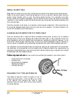
Following operations

 the user is able to do with help of assistant or some other person: 


-


measuring the tyre air pressure 

-


changing tyres 

-


disconnecting the batteries 

-


installing the batteries 

-


changing the lamp 


MEASURING THE TYRE AIR PRESSURE 


The suitable air pressure in the tyre is approx 1.5 bar. Air 

pressure decrease under 1.2 bar and filling over 3.0 bar 

is  not  advised.  This  increases  the  wear  of  tyres, 

decreases grip and causes extra friction, which shortens 

the driving distance.  


Summary of Contents for Four X DL

Page 1: ...MANUAL Read the manual carefully In matters that are unclear we request that you contact us Chasswheel Oy Myllyharjuntie 6 71800 SIILINJ RVI Tel 358 207 559 220 Fax 358 207 559 221 ISO 7176 19 Wheelc...

Page 2: ...and thus improve their quality of life Your CW3 FOUR X DL electric wheelchair guarantees you a smooth ride both on and off road Now there s no need to plan your route according to where your wheelcha...

Page 3: ...wheelchair The warranty does not cover faults caused by normal wear and improper or lack of maintenance as indicated in the owner s manual and the service instructions Furthermore the warranty does n...

Page 4: ...The manufacturer Chasswheel Oy Myllyharjuntie 6 71800 SIILINJ RVI Finland declares that the CHASSWHEEL CW3 FOUR X DL electrically powered wheelchair conforms to the following standard requirements 93...

Page 5: ...SUPPLIES 20 SEAT BELT USE 20 LIGHTING DEVICES 20 TYRES 20 BATTERIES 20 BATTERY RECHARGING 21 FUSES 21 3 DRIVING THE WHEELCHAIR 22 MOUNTING TO THE WHEELCHAIR 22 DRIVE PRACTICE 23 BALANCE ADJUSTMENT 24...

Page 6: ...able for visually disabled blind person badly spastic person whose moves are so uncontrollable that controlling the wheelchair is impossible disabled person who is not able to understand the correct f...

Page 7: ...before driving that the seat is in the correct position Look at the section Balance adjustment Instability can arise when driving on slope if the balance is adjusted incorrectly Adjusting the balance...

Page 8: ...iving properties or damage the controller system The reliability of the wheelchair and the control system is improved if you keep exposure to extreme conditions to a minimum Damaged wheelchair cables...

Page 9: ...on Maximum safe slope 10 Obstacle negotiation ability 100mm General driving restriction Situated on the battery casing rear case Battery connecting diagram situated inside the battery casing cover Mai...

Page 10: ...riven N breaks released the wheelchair can be towed Situated in every fender Attention read the user manual Situated on the supporting frame both sides from the seat Do not push the wheelchair from th...

Page 11: ...R NET www chasswheel com rev 1 2014 05 08 11 2 EQUIPMENT AND THEIR USE...

Page 12: ...heelchair and applies the parking brakes The joystick is also used for adjusting extra operations Joystick with a standard knob is suitable for most users There are different alternatives to this knob...

Page 13: ...MODE button With the MODE button you can navigate the adjustment menu The available menus depend on the programming and the available operations of connected optional equipment Profile button The desi...

Page 14: ...echarging the wheelchair s batteries or to lock the wheelchair Only connecting the proper charger plug or lock key is permitted LCD DISPLAY The state of the driving controller can be observed using th...

Page 15: ...not in control Restricted speed If the speed of the wheelchair is limited because of a sharp turn raised seat the stand support or lift function etc this symbol will be displayed If the wheelchair is...

Page 16: ...the temporary icons are programmed to be seen the icons below will be temporarily displayed by pressing the Speed or Profile buttons Locking The Wheelchair can be locked using the locking key To lock...

Page 17: ...ing the lever on the side of the back rest while reclining the seat or by turning the wheel on the side of the backrest until the desired position is found ELECTRICALLY ADJUSTABLE BACK REST An electri...

Page 18: ...is adjusted by loosening the screws 2 When the suitable position has been found retighten the screws The arm rest height and angle are adjusted with a 5mm hexagonal key Adjusting the height is perfor...

Page 19: ...correct position has been found release the lever The foot support is now locked into this position It is necessary to observe the foot rest position when driving uphill or negotiating obstacles Repe...

Page 20: ...cause of their tread pattern they have a good grip on different surfaces The tyre pressure should be checked regularly Measuring the tyre pressure is defined in section wheelchair servicing BATTERIES...

Page 21: ...recharged immediately if the icon indicating the battery charge level shows only two full pillars Follow the instructions supplied with the charger Use only the charger that has been supplied with the...

Page 22: ...and arm rests can be lifted up as shown in the pictures below Make sure not to damage the controller module and its cable 1 Lift the foot rest up 2 Lift the arm rest up 3 Remove your legs in 4 Be seat...

Page 23: ...e joystick forwards or backwards the wheelchair moves to the direction determined by the current wheel position If the wheels are turned so that the right side wheels are close to each other picture 2...

Page 24: ...e In the drive position for even ground the seat starts to tilt backwards while the balance is shifted backwards The recommended balance positions for driving uphill on even ground and downhill are re...

Page 25: ...balance position backwards and raise the foot rest so that it doesn t hit the step Drive the wheelchair s front wheels onto the step 1 2 Move the balance forwards so that wheelchair s rear part become...

Page 26: ...hair s seat there are attachment rings on the fastening pipes for the arm rests picture 1 to which attachment straps can be fastened during transportation When strapping the wheelchair care must be ta...

Page 27: ...ese operations are mentioned below However the more demanding service operations such as electrical malfunctions driving motors actuators frame parts seat parts foot and arm rests changing the tyres a...

Page 28: ...e may damage the plastic and fabric parts of the wheelchair Follow the recommendations set by the cleaning fluid manufacturers regarding the different materials In the event of the control module beco...

Page 29: ...tor fill up the tyre approx 3bar is reasonable After this remove lifting equipment and the chair is ready to drive again DISCONNECTING THE BATTERIES Detach the cables and and the main fuse from the ba...

Page 30: ...ries by himself if he wants and is able to do it Here is the spare part information for user from the lamps and the batteries Suitable lamps for Four X wheelchair the user can get from the Four X dist...

Page 31: ...g Switch the driving controller on and try to drive the wheelchair If the exclamation mark continues to flash on the display switch the driving controller off Do not use the wheelchair and contact ser...

Page 32: ...ic and upper body safety belts Both types of safety belt should be used in order to minimize the risk of injuries to head or upper body It is imperative that the wheelchair is inspected by an authoriz...

Page 33: ...r is secured within the wheelchair CAUTION There is a danger of injury if the user is not properly secured within the wheelchair Even if the wheelchair is fitted with a postural belt this is no substi...

Page 34: ...applied as shown in the illustration at right 1 Centre line of the body 2 Centre of the sternum Seat belts may not be held at a distance from the user s body using parts of the wheelchair such as arm...

Page 35: ...3 8 kg Seat Recaro standard width 450 mm effective seat depth 522 mm backrest height 682 mm back angle min 12 52 seat surface height at the front edge 570 mm seat plane angle 22 37 Overall dimensions...

Page 36: ...enance done by _________________________________________________________ Date and place ______________________________________________________________ Annual maintenance Yes __ No __ Additional mainte...

Page 37: ...____________________________________________________ Date and place ______________________________________________________________ Annual maintenance Yes __ No __ Additional maintenance if needed ____...

Page 38: ...____________________________________________________ Date and place ______________________________________________________________ Annual maintenance Yes __ No __ Additional maintenance if needed ____...

Page 39: ...____________________________________________________ Date and place ______________________________________________________________ Annual maintenance Yes __ No __ Additional maintenance if needed ____...

Page 40: ...____________________________________________________ Date and place ______________________________________________________________ Annual maintenance Yes __ No __ Additional maintenance if needed ____...

Page 41: ...R NET www chasswheel com rev 1 2014 05 08 41 STAND SUPPORT SYSTEM...

Page 42: ...belt use Knee support use Electric adjustment length compensation for the foot support Centre of gravity adjustment Raising of the seat section Folding of the upper part of the back Head support adjus...

Page 43: ...s the maximum speed automatically when the upright position raiser operation is used If you suspect that the limiter is not operating properly do not use the Stand Support Sysytem but contact service...

Page 44: ...has velcro fastening The knee support is adjusted correctly when it is snapped underneath the kneecap A loosely attached knee support does not give enough support whilst in the erect position SEAT OP...

Page 45: ...centre of gravity is adjusted possibly back the seat is raised higher ADJUSTMENT OF THE BACK SECTIONS The position of the backs can be adjusted when the backs and the horizontal arrow are visibly dar...

Page 46: ...atest safety use gradient 5 Seat spindle motor Linak LA 31 D Back s spindle motor Reac RE 25 Foot rest motor Reac RE 25 SaVer seat standard width 490 mm effective seat depth min 500 mm backrest height...

Page 47: ...R NET www chasswheel com rev 1 2014 05 08 47 LIFT SYSTEM...

Page 48: ...NDATIONS Safe driving 2 EQUIPMENT AND THEIR USE Safety belt use Seat functions adjustment Electric adjustment length compensation for the foot support Centre of gravity adjustment Raising of the seat...

Page 49: ...e raising the lift ensure that the safety accessories are properly attached The appliance is installed with a speed limiter which limits the maximum speed automatically when the lift operation is used...

Page 50: ...pressing the MODE button again you can get back to the drive situation FOOT SUPPORT ADJUSTMENT The angle of the foot support is adjusted by selecting the foot support adjustment from the MODE selectio...

Page 51: ...n the backs and the horizontal arrow are visibly darkened When the seat is rised with lift operation you are not able to adjust the back rest backwards 3 TECHNICAL INFORMATION ON THE LIFT SYSTEM Great...

Reviews: