background image


9


www.chasswheel.com 


Before using and during usage, check the batteries’ charge. Always charge the batteries if they are 
empty  or  low.  The  standard  charging  device  of  the  wheelchair  does  not  allow  the  batteries  to  be 

overcharged.  

The functionality of the wheelchair can be disturbed by electromagnetic fields which can be caused 

by  e.g.  mobile  phones  and  other  similar  devices.  The  wheelchair  itself  can  disturb  other 

electromagnetic devices from functioning, such as shops’ security systems.  

Do not leave the wheelchair exposed to direct sunlight. The wheelchair’s metal parts and surfaces, 

such  as  the  seat  and  arm-rests,  overheat  easily.  Also  avoid  leaving  the  wheelchair  out  in  cold 

weather or frost.   

If You have used the wheelchair in damp conditions, be sure to take care of drying it, e.g. putting it 

into a warm room. Do not leave the wheelchair outside or in a cold/damp room. Failing to follow the 
beforementioned advice can cause damage to the wheelchair.  

SAFE USAGE AND MAINTENANCE 


Factory programmed parameters have been installed into the wheelchair’s control system and they 

are suitable for most users. Some of these parameters can be changed. Programming can only be 

carried  out  by  an  autherised  specialist  who  has  knowledge  of  the  wheel  chairs  control  systems. 

Wrong programming can be hazardous and damage the control systems.  

The wheelchair’s control system should be exposed to extreme conditions as little as possible.  

Damage to the wheelchair’s cables causes a safety issue that should be immediatley reported to an 

autherised technician.  

Check the condition of the tyres on regular basis. It is essential for steering as well as for durability 

of the wheels to have correct tyre pressure. The measurement of tyre pressure has been described 

in the section „Maintenance of the wheelchair“.  

To avoid the usage of the wheelchair without permission, use the locking key (blue). It is hazardous  

if the wheelchair is used by an unauthorized person.  

For transportation, always attach the wheelchair to the body of the car. It is strictly prohibited to sit 

in the wheelchair whilst being transported.  

Repair and alteration works are prohibited without supplier’s authorization.  

The  allowed  maintenance  works  that  can  be  carried  out  by  the  user  are  described  in  section 

“Maintenance of the wheelchair.“ 

If  the  wheelchair  is  being  maintained  or  adjusted,  then  the  control  system  must  be  switched  off. 

Only gel batteries can be used in order to avoid the risk of electrical damage.  

If electric tools are used near the batteries, then one has to consider the possibility of a short-circuit. 

Usage of open fire is prohibited due to a danger of explosion. Battery box is not meant to be used 

for storage of other objects. The wires to the batteries are not to be disconnected by oneself. In 

case of problems, please contact an autherised technician.  

Summary of Contents for FOUR X URBAN

Page 1: ...OWNER S MANUAL Read the manual carefully In matters that are unclear we request that you contact us Chasswheel Oy Myllyharjuntie 6 71800 SIILINJ RVI Tel 358 207 559 220 Fax 358 207 559 221...

Page 2: ...chair guarantees a smooth drive for You on town streets as well as off road You do not have to plan Your routes considering where You can access with a wheelchair and where You cannot as You can move...

Page 3: ...covers defects derived from the regular usage of the wheelchair This warranty does not cover general wear and tear or the damages derived from the misusage of the wheelchair or inproper maintenance T...

Page 4: ...CHASSWHEEL FOUR X URBAN is class B electrically powered wheelchair conforms to the following standard requirements EN 12184 2006 EN 1041 1998 EN ISO 14971 2007 EN12182 1999 ISO 1999 1997 ISO 6440 1985...

Page 5: ...ning blinker on and of 24 Operating the electrical adjustment options 24 Which symbols are displayed and what they mean 24 Entering adjustment mode 25 Selecting and actuating adjustment options 25 Cha...

Page 6: ...TION OF THE WHEELCHAIR 46 6 MAINTENANCE OF THE WHEELCHAIR 47 DAILY CHECKS 47 WEEKLY CHECKS 47 CLEANING OF THE WHEELCHAIR 47 MEASUREMENT OF TYRE S AIR PRESSURE 48 CHANGING OF A WHEEL 48 DISASSEMBLING O...

Page 7: ...oints Consider the possible dangers that might be caused by them especially when using the wheelchair near children and pets Make sure that they are kept at a safe distance from the wheelchair The par...

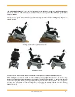
Page 8: ...ions for uphill and downhill Obstacle 150mm Driving in water is prohibited due to the danger of damaging the wheelchair s electric parts When driving the wheelchair in dim or dark conditions driving l...

Page 9: ...e control systems The wheelchair s control system should be exposed to extreme conditions as little as possible Damage to the wheelchair s cables causes a safety issue that should be immediatley repor...

Page 10: ...m incline is 20 degrees Maximum angle is 150 mm Located on the casing s cover in the rear part Instruction for connecting batteries Located on the inside of the casing s cover The size of the main cir...

Page 11: ...ride the wheelchair N brakes are released the wheelchair can be towed Located on both shafts on the side of the brake s protection box NB Read the label located on the right and left side of the lifti...

Page 12: ...550 and R NET JSM Steering lever or Joystick The speed and direction of the wheelchair is adjusted by the steering lever Joystick The further the lever is pushed forward the faster the wheelchair move...

Page 13: ...panel The function of buttons are described in more detail in this chapter If the steering device has been switched on the lights will appear on the screen and the screen will display a function to sh...

Page 14: ...www chasswheel com 14...

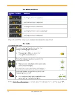
Page 15: ...15 www chasswheel com The Seating Functions The Lights...

Page 16: ...www chasswheel com 16 Battery charge indication Other indications...

Page 17: ...17 www chasswheel com Battery Charging System Lock...

Page 18: ...k and drive profile 2 3 DYNAMIC DX REM550 The driving controller consists of a joystick and control panel Under the driving controller you ll find the charger socket and the data transfer cable which...

Page 19: ...ers There are different alternatives to this knob or the knob can be tailor made Do not replace the knob with self made parts as they may cause dangerous situations 1 Drive lever 2 Display Top side Di...

Page 20: ...ing mode key This key is deactivated as standard The cover cap must be removed if sockets 2 to 5 are to be used To do this remove the Phillips screw Status display Status display The status display is...

Page 21: ...Please charge the batteries immediately The battery symbol illuminates red no bars Driving range exhausted Charge the batteries immediately NOTE To protect against total battery discharge the electro...

Page 22: ...te A Buddy Button 4 is an additional button which can be used to activate remote functions The sockets for Buddy Buttons are located underneath the remote 1 Socket I corresponds to Activate drive mode...

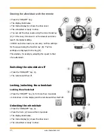
Page 23: ...he speed using the function key B The fine settings are displayed in the ring D This enables for example adapting the speed to that of an attendant Switching the wheelchair off Press the ONN OFF key 1...

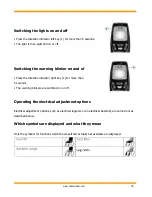
Page 24: ...the direction indicator right key 1 for more than 5 seconds The warning blinkers are switched on or off Operating the electrical adjustment options Electrical adjustment options such as electrical leg...

Page 25: ...wheelchair symbol Selecting and actuating adjustment options Press the function key C under the wheelchair symbol or move the drive lever left or right several times until the required adjustment opti...

Page 26: ...g from setting mode to drive mode Press the Activate drive mode switch through key D The remote will switch back to drive mode The mode display A shows the drive level Further adjustment options Deact...

Page 27: ...ther settings press the Activate setting mode key A or move the drive lever right or left again To return to drive mode press the Activate drive mode switch through key C Setting the time The symbol f...

Page 28: ...ever to the right or left to display or hide the time display If you press the drive lever forwards when two ticks are displayed above the function key B the changes you have made to the time display...

Page 29: ...setting mode key A or move the drive lever forwards to save the change To carry out further settings press the Activate setting mode key A or move the drive lever right or left again To return to driv...

Page 30: ...rors automatically In this case the code number in the status display will disappear To do this switch the remote on and off several times Wait approx 5 seconds each time before switching the remote o...

Page 31: ...ssions turn the wheelchair aid off remove the wheelchair aid from the effecting area by placing brake lever arms in neutral position Then wait 5 minutes and turn the wheelchair aids power back on If t...

Page 32: ...rrently used function is displayed The symbols displayed are defined later in this chapter ON OFF button With the ON OFF button the driving controller can be switched on and off Do not use this switch...

Page 33: ...outdoor driving The maximum speed for the indoor driving profile has been adjusted lower than the speed in the outdoor driving profile Left turn indicator switch By pushing the button the wheelchair s...

Page 34: ...High number of dark pillars indicates good charge level If the icon flashes slowly the battery charge level is low and they should be recharged immediately When the batteries are recharging the pilla...

Page 35: ...ing the symbol will flash Restart When the Restart icon flashes on the display the driving controller must be restarted Fault When the system detects a fault the Fault icon appears on the display Refe...

Page 36: ...displayed by pressing the Speed or Profile buttons Locking The Wheelchair can be locked using the locking key To lock the wheelchair the driving controller has to be switched on The locking key is in...

Page 37: ...e steering lever either to the left or right ADJUSTMENT OF HEADREST In order to adjust the height of the headrest the plastic butterfly nut 1 at the back of the headrest needs to be loosened until the...

Page 38: ...est s bottom angle screw 2 needs to be loosened Once the desired position has been achieved the screws need to be tightened up The height and the angle of the armrest are adjusted with a 5 mm hex key...

Page 39: ...f the footrest the lever 4 needs to be raised after which the lock is released and the position can be adjusted Once the correct position has been gained the lever is released Footrest is locked into...

Page 40: ...ny other batteries otherwise the electric equipment can be damaged Batteries are in the casing s box which is located between the seat and casing s protective cover Instructions for removal and instal...

Page 41: ...chair s release point 80A is installed between the batteries If the fuse has blown the wheelchair s electric function will not work This fuse cannot be changed by the wheelchair s user himself but mus...

Page 42: ...orget to switch off the power of the steering device DRIVE PRACTICE Take your time to get to know the wheelchair s operation as well as settings for different ground conditions such as sand snow ice o...

Page 43: ...left or right Afterwards the steering lever is pushed forwards and only minimal side movements are made until the correct direction has been gained Avoid forceful movements and firstly drive slowly in...

Page 44: ...ving downhill if the seat s rear part has been risen high These incorrect positions can be dangerous Adjust the maximum driving speed to low if you are driving uphill or downhill also when overcoming...

Page 45: ...d not smash into the surface back of the step Get the wheelchair s front wheels on the step 2 1 2 Bring balance adjustment forwards so that the rear part of the wheelchair would be lighter and you cou...

Page 46: ...d off while towing During tow it is forbidden to sit in the wheelchair 5 TRANSPORTATION OF THE WHEELCHAIR The wheelchair can be placed in a vehicle with the help of a ramp or chair lifting device Ever...

Page 47: ...to be handled carefully Make sure that the steering center is attached to the wheelchair Do not fasten up the screws too tightly WEEKLY CHECKS Testing of brakes can be carried out on an even ground w...

Page 48: ...will cause the wearing of the tires reduces the hold of the tires and causes excessive friction which will decrease the carried out distance CHANGING OF A WHEEL Wheel is connected with four hex screw...

Page 49: ...he battery box are in place Place the batteries in the battery box terminals towards the middle part of the chair and put the padding between the walls of the batteries and battery box Connect the bla...

Page 50: ...e LED lamp REAR LAMP Maintenance free LED lamp DIRECTION INDICATOR LAMP Maintenance free LED lamp ELECTRICAL DISTURBANCES IN THE WHEELCHAIR S WORK If the steering device notices a disturbance in the e...

Page 51: ...ructions can be found in section Freewheeling Turn the steering device on and try to move with the wheelchair If a key symbol flashes on the screen then turn the steering device off Do not use the whe...

Page 52: ...km h Drive distance 35 km Batteries 2 x 73Ah gel Motors 4 x 250W User max weight 125 kg Seating width 400 480 mm Seating depth 390 510 mm Backrest height 500 600 mm Ground clearance 6 tire 70mm Slope...

Reviews: