10
Ergostyle ™ FX Tables
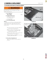
A. Part Numbers
Power Supply
. . . . . . . . . . . . . . . . . . . . . . . . . .58516
B.
Equipment
Required
#2 Phillips Screwdriver
C. Power Supply Removal
1.
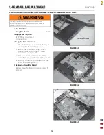
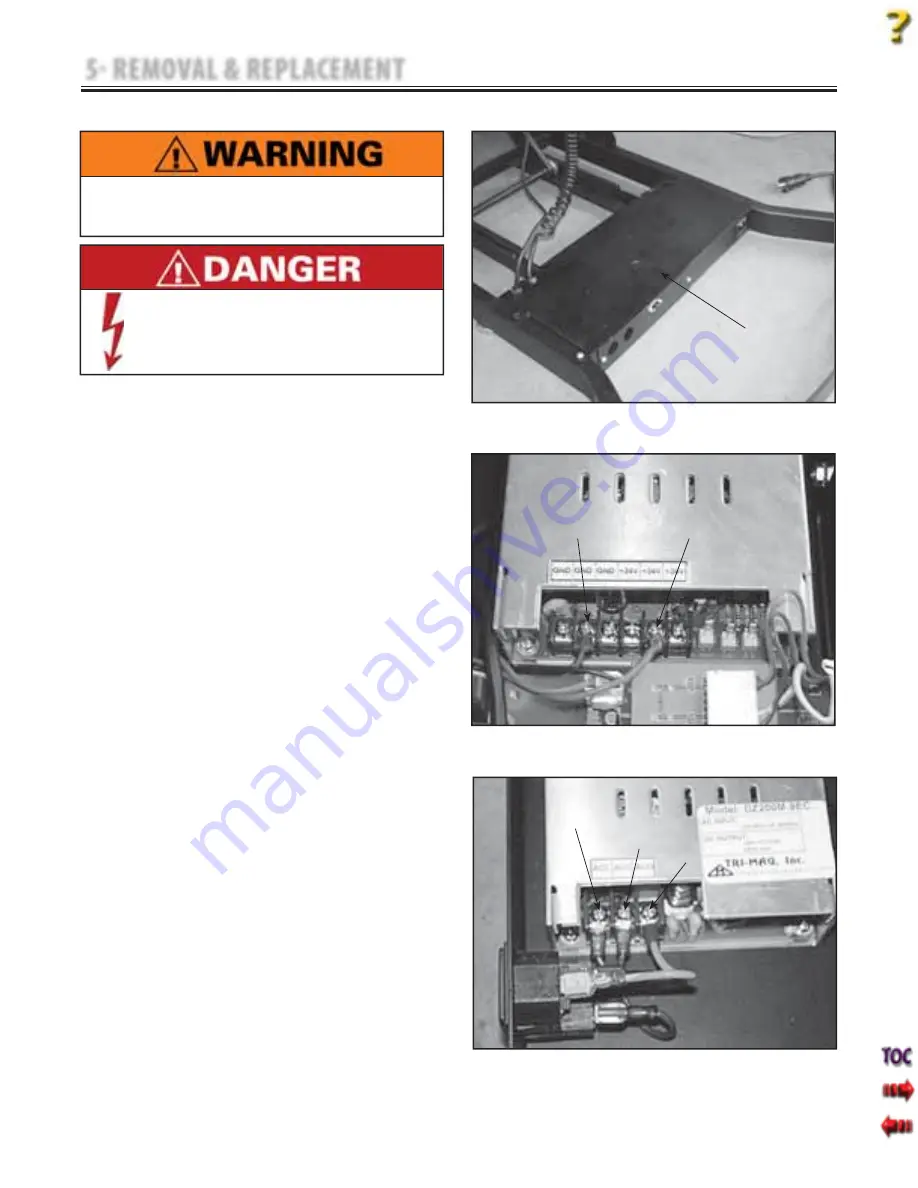
Remove the four Power Supply Cover
Mounting Screws with the #2 Phillips
Screwdriver. See Figure 5.1.
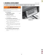
2.
Remove the wires from the output side of
the Power Supply. See Figure 5.2.
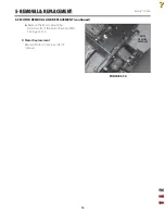
3.
Remove the wires from the input side of the
Power Supply. See Figure 5.3.
NOTE:
Make note of the wire color and locations for
installation to new Power Supply.
•
5 REMOVAL & REPLACEMENT
FIGURE 5.1
FIGURE 5.2
5.1 POWER SUPPLY REMOVAL AND REPLACEMENT
Unplug the unit from the power source before
attempting removal or replacement procedures to
prevent electrical shock.
Power Supplies retain High Voltage!
•
FIGURE 5.3
POWER SUPPLY COVER
BLACK WIRE
BROWN WIRE
RED WIRE
BLUE WIRE
GREEN WITH YELLOW STRIPE WIRE
Summary of Contents for ERGOSTYLE FX 5820
Page 24: ...Ergostyle FXTables 22 8 SCHEMATICS Block Diagram 1 of 1 ...
Page 25: ...Ergostyle FXTables 23 8 SCHEMATICS Pneumatic 1 of 1 ...
Page 26: ...Ergostyle FXTables 24 8 SCHEMATICS Driver Board 58432 1 of 1 ...
Page 27: ...Ergostyle FXTables 25 8 SCHEMATICS Control Board 58433 1 of 1 ...
Page 28: ...Ergostyle FXTables 26 8 SCHEMATICS Daughter Board 58543 1 of 1 ...


