background image

21

SETUP INSTRUCTIONS

EN

INTELECT

®

 RPW 2 USER MANUAL

POWERING UP THE DEVICE

Insert the power cord into the back of the device, insert the 
plug into a power outlet. 
Switch device on with switch on the back of the device.
Make sure the mains connector remain accessible at all 
times as it can serve as an emergency switch. Turn off the 
main rocker switch to completely switch off the device. For 
an all-pole separation from the mains supply, disconnect 
the mains plug from the socket.

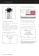
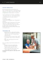
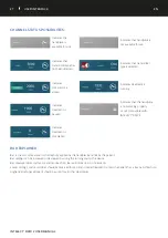
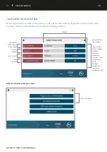
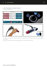
1. The Initialisation screen below will be shown for a
few seconds whilst the device starts.

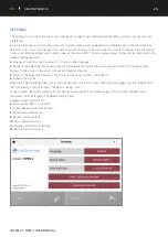
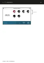
2. The first setup screen will be displayed after this
allowing the user to set language and time in the device.

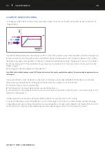
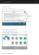
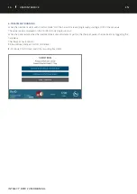
3. If after this step you see the screen below, switch of
the device and follow instructions in point 4 below. If
you do not see this screen the device is ready to use.

4. Insert the supplied USB drive into USB port of device.

5. Switch on the Intelect

®

 RPW 2 device. The device will 

automatically detect software upgrade and install. 

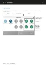
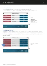
6. Home screen will be displayed when SW update is
finished. 

Important: DO NOT interrupt the process. Do not connect any other 
USB device or connection other than the USB key provided by DJO. 
Electrical dysfunction and device damage could happen.

Summary of Contents for Intelect RPW 2

Page 1: ...Operator and Installation Instructions INTELECT RADIAL PRESSURE WAVE 2 RPW 2 REF 2175KIT 100V REF 2173KIT 120V REF 2174KIT 230V Intelect RPW 2 User Manual EN ...

Page 2: ... 11 PRODUCT DESCRIPTION 11 COMPONENTS 12 IFU DOWNLOAD 13 SYSTEM START UP 13 DEVICE CONNECTED TO THE MAINS 13 TO STOP TREATMENT 13 GENERAL WARNINGS AND 14 PRECAUTIONS CAUTION 14 WARNING 15 DANGER 16 SETUP INSTRUCTIONS 17 UNPACKING THE DEVICE 17 DEVICE DESCRIPTION 19 FALCON HANDPIECE SET UP 20 POWERING UP THE DEVICE 21 SYSTEM 22 OPERATING DATA AND RATINGS 22 FALCON HANDPIECE TECHNICAL SPECIFICATIONS...

Page 3: ...BLE SHOOTING CODES 63 ACCESSORIES 64 REPLACEMENT ACCESSORIES 64 POWER CORDS 64 OPTIONAL ACCESSORIES 65 V ACTOR HF HANDPIECE 66 OPERATIONS SET UP CLEANING AND MAINTENANCE DEVICE DESCRIPTION 66 INSTALLATION INSTRUCTIONS 66 UNPACKING 66 SCOPE OF SUPPLY 66 CONNECTING THE HANDPIECE 67 OPERATION 68 START UP 68 FUNCTIONAL CHECKS 68 STANDARD SETTINGS 68 TREATMENT 70 SAFETY INFORMATION 70 CARRYING OUT TREA...

Page 4: ...E CLEANING 77 MAINTENANCE OVERHAUL CLEANING 77 STANDARD SHOCK TRANSMITTERS 78 SPINE AND FASCIAE SHOCK TRANSMITTERS 79 CLEANING THE HANDPIECE 80 CLEANING THE SHOCK TRANSMITTERS 81 STANDARD SHOCK TRANSMITTERS 81 SPINE AND FASCIAE SHOCK TRANSMITTERS 82 CLUTCH FOR THE SPINE FASCIAE SHOCK 82 TRANSMITTERS OVERHAUL 83 OVERHAULING THE HANDPIECE 83 SERVICE WARRANTY 88 SERVICE LIFE 88 WARRANTY REPAIR OUT OF...

Page 5: ... minor or moderate injury or damage to the equipment Text with a WARNING indicator explains possible safety infractions that will potentially cause serious injury and equipment damage Text with a DANGER indicator will explain possible safety infractions that are imminently hazardous situations that would result in death or serious injury The precautionary instructions found in this section and thr...

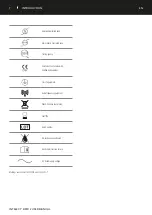
Page 6: ...ameter Setup Custom Protocols Treatment Data Clinical Resources Home Settings USB Drive DESCRIPTION OF DEVICE MARKINGS Refer to Instructional Manual and Quick Start Guide Booklet Warning Caution or Danger Electrical type B equipment Play Pause ON OFF Manufacturer Date of manufacture Catalogue number Serial number Fragile handle with care This end up Keep dry Temperature Range ...

Page 7: ...e Range Testing agency CE Mark of Conformity with notified body number Class 1 equipment Radio frequency equipment WEEE Directive conformity Shelf life Batch number No condensation allowed Read the instruction for use AC Rated supply voltage Markings are conform to ISO7010 and ISO15 223 1 ...

Page 8: ... Increasing Circulation promotes blood flow through the tissue and boosting metabolism Pulse vibration Massage Soothing relief from muscle strain and stress Disorder of Tendon Insertions Plantar Fasciitis heel Pain or heel Spur Plantar Fasciitis is an inflammatory condition of the foot caused by excessive wear to the plantar facia that supports the arch Tendinosis Calcarea Supraspinatus Tendon Sho...

Page 9: ... or reduced sensory and nervous function in the polyneuropathic area Cortisone therapy Wait minimum 6 weeks after local cortisone injection before treatment with radial pressure waves Haemophilia Thrombosis Deep vein thrombosis or other coagulation disorders Anticoagulant pharmaceuticals On any Neoplastic tissues or space occupying lesions Reduced thermal sensitivity over the proposed area of trea...

Page 10: ...ansmitter on the skin with small circular movements Never use Radial Pressure Wave therapy on the head Do not treat direct in an area with a metal implant Patients with active autoimmune diseases may not respond positively with the treatment ADVERSE EFFECTS Side effects could occur after a treatment with Radial Pressure Wave therapy The majority will appear after 1 2 days Do not repeat a treatment...

Page 11: ...jectile produce kinetic energy When the projectile impacts against an immovable surface the shock transmitter this kinetic energy is converted into sound energy This acoustic pulse is transmitted into the tissue to be treated directly with the help of a gel These waves are physically classified as radial pressure waves The applied pressure pulse propagates radially within the tissue and has a ther...

Page 12: ...based with deionized water No formaldehyde no fat For external use only Pouch COMPONENTS Throughout these instructions the terms left and right referring to the device sides are from the perspective of a user standing in front of the device The components of the Intelect RPW 2 are shown below Falcon Handpiece Gel Holder Cable Holders ...

Page 13: ...the back of device Plug the other end of the cord into an electrical outlet Note The Power Cord may be unplugged from the back of the device in an emergency situation 2 Connect the Falcon handpiece on the right connector 3 Turn on the power switch located on the back of the device TO STOP TREATMENT Press Play Pause button to pause treatment then press Stop on touch screen If device is on mains pow...

Page 14: ...ng compatible with the Intelect RPW 2 System DO NOT disassemble modify or remodel the device or accessories This may cause device damage malfunction electrical shock fire or personal injury Before using the therapy device the operator must ascertain that it is in correct working order and operating condition The cables and connectors in particular must be checked for signs of damage The device can...

Page 15: ...e is designed to comply with electromagnetic safety standards This equipment generates uses and can radiate radio frequency energy and if not installed and used in accordance with instructions for use may cause harmful interference to other devices in the vicinity Harmful interference to other devices can be determined by turning this equipment on and off Try to correct the interference using one ...

Page 16: ...ructed to operate only on the electrical voltage specified on the Voltage Rating and Serial Number Plate Contact your DJO dealer if the device is not properly rated Device is not designed to be used in oxygen rich environment Explosion hazard if the device is used in the presence of flammable anesthetic mixture with air oxygen or nitrous oxide If the device is not safe for operation it must be rep...

Page 17: ...d accessories for possible damage due to transport 3 Verify that the packaging contains the following Intelect RPW 2 device Intelect RPW 2 Quick Start Guide USB Stick Pouch Gel Holder Cables Holder Power cord Conductor Transmission Gel 250 ml 8 5 oz bottle Standard Accessory Kit that Includes the following RPW Falcon Handpiece Applicator Projectile R0 40 15 mm ESWT Transmitter D20 S D ACTOR 20 mm ...

Page 18: ...n the any side of the device 7 The cable holder is used to hang the handpieces cables Throughout these instructions the terms left and right referring to the machine sides are from the perspective of a user standing in front of the device The components of the Intelect RPW 2 are shown below ...

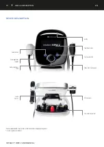
Page 19: ...r Touch Screen Play pause button Falcon Hand Piece Support Transmitter Tray Holder USB Connector Rotary adjustment knob V actor applicator support Switch ON OFF Power Button Device delivered with 2 transmitters Other transmitters displayed are optional V actor applicator is optional ...

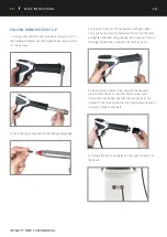
Page 20: ... until finger tight Using one hand press the handpiece firmly onto the table and tighten the shaft using the open end spanner It must no longer be possible to unscrew the shaft by hand 4 Screw the transmitter screw cap with the required transmitter firmly back onto the shaft For two part transmitter caps Make sure that the two cap parts are screwed firmly in place and that the transmitter screw ca...

Page 21: ...wn for a few seconds whilst the device starts 2 The first setup screen will be displayed after this allowing the user to set language and time in the device 3 If after this step you see the screen below switch of the device and follow instructions in point 4 below If you do not see this screen the device is ready to use 4 Insert the supplied USB drive into USB port of device 5 Switch on the Intele...

Page 22: ...upling Pulse Width approx 6 12 ms Pulse Frequency 1 21 Hz for RPW 1 50 Hz for Vibration Fuses 2 x T6 3A H 250 V 5x20 mm Electrical Class CLASS I Electrical Type Degree of Protection TYPE B Regulatory Risk Class IIa according to MDD 93 42 EEC Mass 29 Kg 64 lbs Safe Working Load 5 Kg 11 lbs FALCON HANDPIECE TECHNICAL SPECIFICATIONS Compressed air input 1 0 5 0 bar Ambient temperature during operatio...

Page 23: ...that other treatment methods can t improve or heal RPW therapy is very well perceived among therapists thanks to its positive outcomes and its relatively short treatment period TREATMENT TIPS Let your patient rest in a relaxing position during a treatment session providing them a rolled up towel under their limb for comfort if needed during an elevated treatment Localise the painful points you pla...

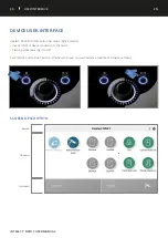
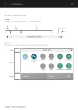
Page 24: ...s several light indicators steady ON from device connection to the mains Flashing while powering ON OFF PLAY PAUSE button blue indicator it flashes when user can start resume a treatment Otherwise steady SCREEN DESCRIPTION DEVICE USER INTERFACE 1 Menu Bar 2 Main Area 3 Channel Bar ...

Page 25: ... areas Menu Bar Located at the top of each screen and lists the current screen name Main area Located under the menu bar this area displays icons unique to the current screen 1 Menu Bar 2 Main Area 3 Channel Bar Go to Home Screen Go to Previous Screen USB Settings Current Screen Name ...

Page 26: ...ed please see page 64 for details The left side of the screen will tell you what transmitter you have selected with an image of the transmitter ensure you have the proper transmitter on the end of the handpiece The right side will tell you pulse count treatment status handpiece selected therapy The treatment status will change as the treatment progresses in generally the following order Set up Arm...

Page 27: ...he handpiece is not working properly or not compatible with INTELECT RPW 2 Indicates treatment is completed BAR EXPLAINED Bar is the unit of measure for the intensity applied by the handpiece and felt by the patient Bar settings can be increased or decreased by using the turning dial on the device Bar measurements start at 0 3 and can reach 5 0 Bar will increase in 0 1 increments Lower settings su...

Page 28: ...ar level the device can be paused When resuming the treatment from being paused the treatment can progress in one of three ways 1 Continue to ramp to the full treatment Bar 2 The treatment can resume at Bar level when paused during ramp up 3 The treatment can be resumed and the clinician can turn the dial on the device so that the ramp is on a lower setting for the remainder of the treatment The B...

Page 29: ...name Select the Device name use the displayed keyboard to enter a new name and confirm The device name displays on the Home Screen and on the patient treatment reports 4 Date Time Select the Date and Time box to set the date and time on the device 5 Screens and sounds Brightness Select the Brightness icon to set the brightness of the LCD screen The brightness ranges from 50 dimmest to 100 brightes...

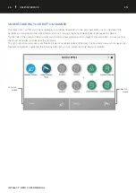
Page 30: ... the system modalities and functions The Home screen has the following information Modalities Assign or launch Shortcut Libraries Clinician protocol library Suggested Parameter Setup Pre programmed protocol library Educational library Modality descriptions Anatomical images Pathological images Treatment data storage ...

Page 31: ...de the following information Save Overwrite default settings or Custom Protocols Treatment guidelines Assign treatment Parameters Select transmitter sub menu screen Select transmitter type Select Transmitter Swipe vertically to see more parameters 1 Touch to activate Active box surrounded by black line 2 Adjust with Adjustment dial Clockwise Increase Counterclockwise Decrease Note When a parameter...

Page 32: ...32 USER INTERFACE EN INTELECT RPW 2 USER MANUAL Select transmitter ...

Page 33: ...ines 33 USER INTERFACE EN INTELECT RPW 2 USER MANUAL Touch image to view in full screen mode Swipe horizontally for more RADIAL PRESSURE WAVE OPERATION Complete the following steps to begin treatment 1 Prepare patient for Radial Pressure Wave treatment Refer to the PATIENT PREPARATION section 2 Select Falcon handpiece icon from the home screen ...

Page 34: ...djustment dial Clockwise Increase Counterclockwise Decrease 4 TRANSMITTER SELECTION Once selecting the transmitter type button as shown previously a screen showing four types of transmitter options will be displayed The second screen will show a listing of the transmitters available for that particular type of transmitter option Touch the transmitter you wish to use Once selected the information w...

Page 35: ...OMFORT MODE ON Press the start pause button The compressor is arming for a few second then when the message armed is displayed the treatment can start by triggering the handpiece The button on the top of the handpiece is the trigger button also called the start stop button ...

Page 36: ...rting at 1 10 of the set value The actual value is displayed on the Comfort mode progression bar When the patient states that the treatment feels uncomfortable or painful the therapist pauses the treatment by triggering the handpiece The therapist has 2 options 1 Resume treatment at Comfort mode level 2 Continue Comfort level search by resuming treatment ...

Page 37: ...ng The handpiece button is pressed projectile stops moving but the handpiece remains active The button on the handpiece is pressed again the projectile resumes movement and treatment can resume Scenario 2 handpiece is active and projectile is moving The device pause button is pressed projectile stops moving but the handpiece remains active The handpiece button is pressed but nothing happens The de...

Page 38: ...ng Stop treatment the treatment will end and treatment summery displayed 9 SINGLE SHOT MODE The Falcon D Actor has the ability to do single shots This can be done by selecting Frequency and turning the dial to the left so that the Hz is displayed as Then select Pulses and change the pulse count to 1 When this single shot treatment is complete the Treatment summery screen will be displayed ...

Page 39: ...completed the Treatment Summary screen will appear with the following options Repeat the treatment by pressing the Run again box Save therapy information to Treatment Data the treatment protocol to the Custom Protocols Exit Modality and return to home screen Settings of completed treatment ...

Page 40: ...ed by the user and the suggested algorithm will select the parameter settings All settings can be edited to suit appropriate patient treatment prescription and patient comfort COMPLETE THE FOLLOWING STEPS TO START AN SPS PROTOCOL 1 Select SPS from the Home Screen 2 Touch the BODY PART you wish to treat Note the selected body part will be highlighted and moving your finger to another area while hol...

Page 41: ...41 USER INTERFACE EN INTELECT RPW 2 USER MANUAL 3 Select INDICATION Select Pressure Wave 4 Select INDICATION Select Pain Zone treatment ...

Page 42: ... UP TREATMENT On the treatment review screen the suggested treatment settings are displayed and you can adjust parameters to desired level Select Radial Pressure Wave Parameters 1 Touch to activate 2 Adjust with Adjustment dial Clockwise Increase Counterclockwise Decrease ...

Page 43: ...43 USER INTERFACE EN INTELECT RPW 2 USER MANUAL 7 START TREATMENT Press the START button Treatment Running ...

Page 44: ...UAL TREATMENT DATA After a treatment has been completed Treatment data can be saved on the Intelect RPW 2 for later use on the device SAVE TREATMENT DATA 1 Touch ASSIGN TO on the Treatment Summary screen 2 Select ASSIGN TO to save Treatment Data ...

Page 45: ...NTERFACE EN INTELECT RPW 2 USER MANUAL 3 The TREATMENT DATA screen appears Save treatment data by selecting ADD Create save to new ID Select save to existing ID SAVE TREATMENT DATA TO A NEW ID Enter ID and Save ...

Page 46: ...46 USER INTERFACE EN INTELECT RPW 2 USER MANUAL VIEW AND MANAGE TREATMENT DATA Press the TREATMENT DATA ICON on the home screen 1 VIEW Treatment Data Select Treatment Data ...

Page 47: ...INTELECT RPW 2 USER MANUAL Select session to view Treatment Summary for that session The TREATMENT HISTORY is displayed including all previously saved treatment sessions ranked chronologically Session details are displayed ...

Page 48: ...48 USER INTERFACE EN INTELECT RPW 2 USER MANUAL 2 DELETE Treatment Data Delete all IDs Delete one ID ...

Page 49: ...49 USER INTERFACE EN INTELECT RPW 2 USER MANUAL Confirm or cancel Delete all treatment sessions ...

Page 50: ...50 USER INTERFACE EN INTELECT RPW 2 USER MANUAL Delete one session ...

Page 51: ...ined SAVE A CUSTOMIZED PROTOCOL A new custom protocol may be saved at either the Treatment Review or Treatment Summary screen 1 Touch SAVE on the TREATMENT REVIEW or TREATMENT SUMMARY screen 2 Select SAVE TO CUSTOM PROTOCOLS Note it is also possible the overwrite the default settings of the modality instead of saving to custom protocols ...

Page 52: ...ry is displayed where you can save the protocol as NEW custom protocol or OVERWRITE an existing custom protocol CREATE NEW CUSTOM PROTOCOL Enter Custom Protocol Name and Save Select and overwrite existing protocol Alphabetical list Swipe to see more Create new custom protocol ...

Page 53: ...53 USER INTERFACE EN INTELECT RPW 2 USER MANUAL VIEW AND MANAGE CUSTOM PROTOCOLS Touch the CUSTOM PROTOCOLS icon on the Home Screen 1 VIEW Custom Protocol Select desired Custom Protocol ...

Page 54: ... USER INTERFACE EN INTELECT RPW 2 USER MANUAL The TREATMENT REVIEW SCREEN is displayed showing the protocol settings Start treatment or perform other actions 2 DELETE custom protocol Delete all protocols ...

Page 55: ...55 USER INTERFACE EN INTELECT RPW 2 USER MANUAL Delete one protocol ...

Page 56: ...rtcut assignments on the home screen ASSIGN SHORTCUT Complete the following steps to assign a home screen shortcut unassigned Short cut icons appear grey in color for a customized protocol Press one of the unassigned Shortcut icons on the home screen Select the desired protocol in the Custom Protocol library ...

Page 57: ...57 USER INTERFACE EN INTELECT RPW 2 USER MANUAL Shortcut assigned on home screen Once assigned the shortcut icon becomes the color associated with the modality it contains ...

Page 58: ...the Home screen press and hold the shortcut icon you wish to unassign The device will display a text box asking Remove My Custom Protocol 1 shortcut Select No to quit the unassignment process and return to the Home screen or Yes to continue with the unassignment process After selecting Yes the previously assigned shortcut will no longer appear on the Home screen ...

Page 59: ... clinician to use with the patient The modality descriptions provide information about the physical background and physiological effects of the Radial Pressure Wave and Vibration therapy aiming to assist the user in selecting the appropriate modality Complete the following steps to view the Clinical Resources Library Press the Clinical Resources Library icon on the Home screen ANATOMICAL PATHOLOGI...

Page 60: ...2 Touch the body part for which you wish to view information Choose either anterior on left of screen or posterior on right of screen 3 The available images for the selected body part are displayed Touch the image you want to see in full screen mode ...

Page 61: ...61 USER INTERFACE EN INTELECT RPW 2 USER MANUAL 4 Full screen image Close full screen mode ...

Page 62: ...nt screen for example to print a treatment session this performed by 1 Insert USB drive into the USB port on the back of the Intelect RPW 2 device 2 Press the play pause button and the On Off button simultaneously for around 1 second the screen will flash and the image is captured on the USB drive 3 In the setting menu eject the USB drive to enable safe removal from the Intelect RPW 2 device 4 The...

Page 63: ... 2 If System error occurs note error code and contact DJO selling dealer or DJO Service Department 3 In case a red triangle is shown click on the triangle to get an explanation internationalproductsupport djoglobal com If the device is not powering on display and lights do not switch on 1 Check that ON OFF button on the rear of the device is ON 2 Check the power cable is connected to proper alimen...

Page 64: ... 28178 Ro40 Beam Transmitter 29724 D20 S D Actor 20mm Transmitter 29104 Revision Kit Short 15 1140 USB Key 22651 Gel cup and holder 82 0274 RPW Pouch 22652 Transmitter tray 13 7611 1 Cable holder 22654 Water reservoir 13 28660 Quick Start Guide Available in multiple languages with each unit POWER CORDS Model Number Description 14679 Power cord North American 14814 Power cord Switzerland 40 0108 Po...

Page 65: ...r 28736 D20 T Transmitter 29725 D35 S 35 mm D Actor Transmitter Black 29539 ATLAS Transmitter 28946 INTELECT RPW 2 SPINE ACTOR Transmitter set 28945 INTELECT RPW 2 PERI ACTOR Transmitter set 19365 V Actor HF 28740 V Actor V25 Transmitter 28741 V Actor V40 Transmitter 29742 V Actor V10 Transmitter without transmitter screw cap 4248 CONDUCTOR US Gel 24x 8 5oz BOTTLES 4238 CONDUCTOR US Gel 5L Cube w ...

Page 66: ...llowing three shock transmitter heads 1 V ACTOR HF spherical vibration transmitter 10 mm V10 2 V ACTOR HF vibration transmitter 25 mm V25 3 V ACTOR HF vibrationtransmitter 40 mm 1 1 Trigger button 2 2 Shock transmitter 3 INSTALLATION INSTRUCTIONS UNPACKING Remove the handpiece and accessories from the packaging container Check that all items are included in the packaging container and that they ar...

Page 67: ...ommended that the connector plug on the left side is used Insert the plug of the handpiece into the handpiece connector on the Intelect RPW 2 Make sure that the red dot on the plug is aligned with the red dot on the handpiece connector Gently pushing the plug into the connector will immediately lock the access and will prevent the connector from disengaging automatically when the cable is pulled P...

Page 68: ...lled Set the energy level in V ACTOR HF mode to 2 4 bar Reset the actual number of pulses on the display of the control panel Release pulses with a pulse frequency of 30 Hz Check that the triggered pulses are correctly counted on the treatment pulse counter of the control device STANDARD SETTINGS Before each treatment make sure that the pulse counter is set to zero Start the V ACTOR HF treatment a...

Page 69: ...r Frequency Hz 2 4 50 2 5 46 2 6 42 2 7 41 2 8 39 2 9 38 3 0 36 3 1 35 3 2 34 3 3 33 3 4 31 3 5 30 3 6 28 3 7 27 3 8 26 3 9 25 4 0 24 4 1 23 4 2 22 4 3 21 4 5 20 4 6 19 4 8 18 5 0 17 The chart shown here displays the relationship between pressure and frequency when using the V Actor HF with the Intelect RPW 2 ...

Page 70: ... patient undue pain under any circumstances CARRYING OUT TREATMENT Apply a sufficient amount of massage oil to the patient s skin in the treatment area and to the V ACTOR HF vibration transmitter Perform V ACTOR HF treatment as recommended in the application brochure application recommendations V Actor is a registered trade mark of Storz medical AG Caution The handpiece may not be operated while i...

Page 71: ...To remove the V40 vibration transmitter unscrew the vibration transmitter from the handpiece Unscrew the vibration transmitter screw cap 1 and 5 and pull out the shock transmitter Remove the sealing ring 3 by pressing it apart at the cut through point 6 To clean press the spring element 4 together slightly and remove the residue underneath it Do not attempt to remove this portion of the transmitte...

Page 72: ...h use The vibration transmitters can be cleaned using the usual cleaning agents and disinfectants after each use As an alternative you may clean the vibration transmitters each day in an ultrasonic bath Caution Cleaning agents and disinfectants may generate an explosive atmosphere Disconnect the handpiece from the control device before starting any cleaning or maintenance work Attention It is esse...

Page 73: ...ibration transmitter from the handpiece Remove the vibration transmitter insert from the front cap The spring element 1 on the vibration transmitter insert does not need to be removed Clean all of the parts under running water Alternatively you can clean and disinfect the vibration transmitter insert and the sealing ring in an ultrasonic bath V40 Unscrew the vibration transmitter from the handpiec...

Page 74: ... description Possible cause Corrective actions No compressed air supply Leaks in handpiece cable or cable not properly connected Check the cable and tube connections and replace them if necessary No power output Handpiece defective Replace the handpiece Accessories Art no V ACTOR HF handpiece set 19365 25 mm vibration transmitter 28740 40 mm vibration transmitter 28741 10 mm spherical vibration tr...

Page 75: ... the repair label filled in completely Missing components will be replaced subject to charge Accessories also sent will be checked and if necessary replaced after we have assessed them Vibration transmitters and overhaul kits are not covered by the handpiece s warranty SERVICE Should you have any further questions or require additional information please feel free to contact your dealer See page 8...

Page 76: ...vailability 6 Confirm firmware update DEVICE MAINTENANCE No internal maintenance or routine calibration is required for the device itself For the Falcon and V Actor HF handpieces along with the transmitters please refer to the correct section in this user manual Power cable replacement Unplug the default cable then plug the new cable Falcon and V Actor are registered trade marks of Storz medical A...

Page 77: ...g Component Procedure Interval Handpiece shaft and cushion clean and disinfect daily or after 20 000 shocks whichever comes first Guide tube clean from inside with brush every day Shock transmitters and O rings clean in ultrasonic bath and disinfect after each treatment or contact with a patient Guide tube projectile and O rings replace after 1 000 000 shocks overhaul the handpiece Caution Flammab...

Page 78: ...ding shock transmitter screw cap 5 Screw the shock transmitter screw cap onto the handpiece until finger tight 6 After replacing the shock transmitter make sure that the handpiece cap and the cap parts are screwed firmly in place Note Make sure that the cap parts of the shock transmitters are screwed firmly in place and that the shock transmitter screw cap is screwed firmly to the shaft Check the ...

Page 79: ...e clutch onto the handpiece 3 Take out the desired shock transmitter from the case 4 Push the inner part of the clutch in direction to the shaft of the handpiece 1 Push the shock transmitter into the clutch 2 5 Release the inner part of the clutch The shock transmitter engages into its place Note Before starting with treatment make sure that the shock transmitter is engaged into its place 6 To dis...

Page 80: ... 3 Clean the coupling gel off the handpiece using a cleaning agent that is suitable for surface cleaning Disinfect the handpiece with an alcohol based disinfectant that is suitable for surface cleaning 4 Unscrew the shaft from the handpiece and pull it out of the handpiece handle 5 Use the supplied open end spanner 4 for this purpose 5 Clean the guide tube with a brush in order to ensure perfect p...

Page 81: ...hock transmitter insert from the shock transmitter screw cap Clean all of the parts under running water Note The shock transmitter insert of two part transmitter caps can only be dismantled and the sealing rings can only be removed using special tools You should avoid doing this because it could result in damage to the shock transmitter It is not necessary for cleaning purposes ...

Page 82: ...ter screw cap is screwed firmly to the shaft Check the screw connection of the shock transmitter screw cap and cap parts during prolonged treatment phases SPINE AND FASCIAE SHOCK TRANSMITTERS Remove the applicator from the handpiece and disconnect it from the coupling Remove the residuals of coupling gel immediately after each treatment with a damp cloth Note If coupling gel remains on the applica...

Page 83: ...ing rings the projectile and the guide tube must always be replaced each time the handpiece is overhauled Observe the O ring Guide when selecting the sealing rings to be used It is contained in the overhaul kit OVERHAULING THE HANDPIECE Flammable and volatile cleaning and disinfecting agents may generate an explosive atmosphere Disconnect the handpiece from the control unit before starting any cle...

Page 84: ...ll the tightly fitting guide tube out of the shaft If necessary use a thin metal rod or the supplied hexagonal spanner as a pulling tool by inserting it through the openings in the guide tube 4 A corresponding fixture is provided in the handpiece handle to hold back the projectile To remove the projectile hold the handpiece handle with its opening pointing down Gently knock the handle against the ...

Page 85: ...nsmitter screw cap using a disinfectant containing alcohol These are reused after cleaning Note The shock transmitter insert of two part transmitter caps can only be dismantled and the sealing rings can only be removed using special tools You should avoid doing this because it could result in damage to the shock transmitter It is not necessary for cleaning purposes 8 Now from the overhaul kit take...

Page 86: ...t the new projectile into the fitted guide tube 12 Screw the shaft into the handpiece until finger tight Using one hand press the handpiece firmly onto the table and tighten the shaft using the open end spanner It must no longer be possible to unscrew the shaft by hand 13 Screw the transmitter screw cap with the required transmitter firmly back onto the shaft For two part transmitter caps Make sur...

Page 87: ...shocks for the clutch Exceeding the service life can be expected to result in a failure of the devices No warranty claims shall be accepted beyond the information given SERVICE LIFE OF THE V ACTOR HF HANDPIECE The average expected service life of the handpiece is approx 5 million pulses Exceeding the service life can be expected to result in a failure of the devices No warranty claims shall be acc...

Page 88: ...eces and other accessories Shelf life is indicated on the gel bottle itself Handpiece Repair Repair work on defective handpieces must only be carried out by personnel suitably authorised by DJO Global Only original DJO Global parts may be used for this purpose The suitably authorised personnel can be from DJO Global or be representatives of DJO Global agencies and dealers DISPOSAL Intelect RPW 2 W...

Page 89: ...e proper revision of the handpiece is performed every 1 million shocks This Warranty Does Not Cover Replacement parts or labor furnished by anyone other than the Company the selling dealer or a certified Company service technician Defects or damage caused by labor furnished by someone other than Company the selling dealer or a certified Company service technician Any malfunction or failure in the ...

Page 90: ... in healthcare facilities developed with FDA participation by the Association for the Advancement of Medical Instrumentation AAMI Technical Information Report TIR 18 Guidance on Electromagnetic Compatibility of Medical Devices for Clinical Biomedical Engineers AAMI TIR 18 1997 Arlington Virginia Association for the Advancement of Medical Instrumentation 1997 Caution Medical electrical equipment re...

Page 91: ... RPW 2 The Intelect RPW 2 should not be used adjacent to or stacked with other equipment If adjacent or stacked use is necessary Intelect RPW 2 should be observed to verify normal operation in the configuration in which it will be used If you detect damage or malfunctions that may impair the safety of the patient or of the operator have the device repaired before using it If it is necessary to rep...

Page 92: ...of the Intelect RPW 2 device requires continued operation during power mains interruptions it is recommended that the Intelect RPW 2 device be powered from an uninterruptible power supply or a battery Power frequency 50 60 Hz magnetic field to IEC 61000 4 8 30 A m 30 A m Power frequency magnetic fields should be at levels characteristics of a typical location in a typical commercial or hospital en...

Page 93: ... 217Hz 28 V m 800 960 MHz PM 18 Hz 28 V m 1 7 1 99 GHz PM 217 Hz 28V m 2 4GHz 2 57GHz at PM 217Hz 9V m 5 1GHz 5 8GHz at PM 217Hz 27 V m 380 390MHz PM 18Hz 28 V m 430 470MHz FM 5kHz 1 kHz sine 9 V m 704 787 MHz PM 217Hz 28 V m 800 960 MHz PM 18 Hz 28 V m 1 7 1 99 GHz PM 217 Hz 28V m 2 4GHz 2 57GHz at PM 217Hz 9V m 5 1GHz 5 8GHz at PM 217Hz Field strengths from fixed transmitters such as base statio...

Page 94: ... identified an audio signal sounds the device stops immediately the message ERROR and an error code appear on the display In this case you may attempt to restart the device by turning it briefly off and on with the power switch WARNING Portable RF communications equipment including peripherals such as antenna cables and external antennas should be used no closer than 30 cm 12 inches to any part of...

Page 95: ...0 EN Rev C DJO France SAS Centre Européen de Frêt 3 rue de Bethar 64990 Mouguerre France T 33 0 5 59 52 86 90 F 33 0 5 59 52 86 91 DJOglobal com Copyright 2019 by DJO LLC All rights reserved No part of this publication may be reproduced distributed or transmitted in any form or by any means ...

Reviews: