background image


Page 14 of 22 

Intimidator™ Scan LED 200 User Manual (Rev. 02a) 

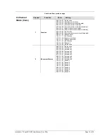
DMX Channel Assignments and Values 


8-Channel Mode 


Channel 

Function 

Value 

Setting 


Pan 

000 

ó

 255  0°~180° 


Tilt 

000 

ó

 255  0°~90° 


Color 

000 

ó

 007 

008 

ó

 015 

016 

ó

 023 

024 

ó

 031 

032 

ó

 039 

040 

ó

 047 

048 

ó

 055 

056 

ó

 063 

064 

ó

 071 

072 

ó

 079 

080 

ó

 087 

088 

ó

 095 

096 

ó

 103 

104 

ó

 111 

112 

ó

 119 

120 

ó

 127 

128 

ó

 191 

192 

ó

 255 

Open (white) 
Dark Blue 
Yellow 
Pink 
Green 
Red 
Blue 
Salmon Pink 
White/dark blue 
Dark blue/yellow 
Yellow/pink 
Pink/green 
Green/red 
Red/blue 
Blue/salmon pink 
Salmon pink/white 
Rotate clockwise (slow ~ fast) 
Rotate counter-clockwise (slow ~ fast) 


Shutter 

000 

ó

 003 

004 

ó

 007 

008 

ó

 215 

216 

ó

 255 

Closed 
Open 
Strobe (slow ~ fast) 
Open 


Dimmer 

000 

ó

 255  0%~100% 


Gobo Wheel 

000 

ó

 007 

008 

ó

 015 

016 

ó

 023 

024 

ó

 031 

032 

ó

 039 

040 

ó

 047 

048 

ó

 055 

056 

ó

 063 

064 

ó

 071 

072 

ó

 079 

080 

ó

 087 

088 

ó

 095 

096 

ó

 103 

104 

ó

 111 

112 

ó

 119 

120 

ó

 127 

128 

ó

 191 

192 

ó

 255 

Open 
Gobo 1 
Gobo 2 
Gobo 3 
Gobo 4 
Gobo 5 
Gobo 6  
Gobo 7  
Gobo 7 shake, fast to slow 
Gobo 6 shake, fast to slow 
Gobo 5 shake, fast to slow 
Gobo 4 shake, fast to slow 
Gobo 3 shake, fast to slow 
Gobo 2 shake, (fast 

ó

 slow) 

Gobo 1 shake, (fast 

ó

 slow) 

Open 
Gobo scroll: Clockwise rotation 
Gobo scroll: Counter-clockwise rotation 


Continues on the next page 


Summary of Contents for INTIMIDATOR 200

Page 1: ...User Manual...

Page 2: ...gging 9 4 Operation 10 Control Panel Operation 10 Menu Map 10 DMX Operation 11 Starting Address 11 Standalone Operation 12 Master Slave Mode Sound Active Auto Mode 12 Automatic Slow 12 Automatic Fast...

Page 3: ...can be chosen Settings A menu option not to be modified for example showing the operating mode current status Menu Settings A sequence of menu options to be followed ON A value to be entered or selec...

Page 4: ...roduct in a location with adequate ventilation at least 20 in 50 cm from adjacent surfaces Be sure that no ventilation slots on the unit s housing are blocked Always disconnect this product from the p...

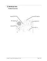
Page 5: ...Intimidator Scan LED 200 User Manual Rev 02a Page 5 of 22 2 INTRODUCTION Product Overview Power Out DMX In DMX Out Power In Microphone Fuseholder...

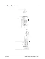
Page 6: ...Page 6 of 22 Intimidator Scan LED 200 User Manual Rev 02a Product Dimensions...

Page 7: ...or fuse making sure that it has an appropriate electrical ground to avoid the risk of electrocution or fire Never connect this product to a rheostat variable resistor or dimmer circuit even if the rhe...

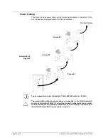
Page 8: ...n Power Linking Diagram You can power link up to 8 Intimidator Scan LED 200 units on 120 VAC The power linking diagram shown above corresponds to the North American version of this product ONLY If usi...

Page 9: ...igging point whether an elevated platform or a truss When rigging this product onto a truss you should use a mounting clamp of appropriate weight capacity The bracket has a 13 mm hole which is appropr...

Page 10: ...ctivate a menu option or a selected value Menu Map Menu Selection 1 Selection 2 Description DMX Address d001 512 DMX starting address Standalone Mode SLAv Son Standalone Slave receive mode nStS SrUn S...

Page 11: ...ould restrict the access to some of the fixture s channels The Intimidator Scan LED 200 uses up to 8 DMX channels in its 8 channel DMX mode which defines the highest configurable address to 505 If you...

Page 12: ...er explanation 1 Press MODE ESC until one of the standalone modes appears on the LED screen SLAu nStS nAFA nASL 2 Using UP and DOWN select nASL 3 Press ENTER Automatic Fast This fixture has a preprogr...

Page 13: ...ustment for tilt 9128 000 255 Adjustment for the gobo wheel C128 000 255 Adjustment for the color wheel H128 000 255 Adjustment for pan Y128 000 255 Adjustment for tilt Please see the instructions bel...

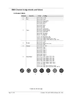
Page 14: ...on pink Salmon pink white Rotate clockwise slow fast Rotate counter clockwise slow fast 4 Shutter 000 003 004 007 008 215 216 255 Closed Open Strobe slow fast Open 5 Dimmer 000 255 0 100 6 Gobo Wheel...

Page 15: ...ck Color wheel move in black disabled Gobo wheel move in black Gobo wheel move in black disabled No Function All movement move in black disabled Reset pan tilt No Function Reset color wheel Reset gobo...

Page 16: ...lue salmon pink Salmon pink white Rotate clockwise slow fast Rotate counter clockwise slow fast 4 Shutter 000 003 004 007 008 215 216 255 Closed Open Strobe slow fast Open 5 Gobo Wheel 000 007 008 015...

Page 17: ...til the fixture is cold Use a vacuum or dry compressed air and a soft brush to remove dust collected on the external surface vents and reachable internal components Clean the mirror and lens with a mi...

Page 18: ...se the right fader s on the controller Wrong DMX personality on the fixture Set the correct DMX fixture s personality Assign the faders accordingly Wrong polarity setting on the DMX controller Change...

Page 19: ...ht to use its own discretion to repair or replace returned product s Claims The carrier is responsible for any damage incurred during shipping to this product or any part that shipped with it Therefor...

Page 20: ...er will control fixture A This means that the user should assign the starting address of fixture B to 005 or higher For a starting address of 005 the DMX controller would use channels 005 to 010 to co...

Page 21: ...connector on the other end The DMX protocol indicates that the XLR connectors must have five pins However most lighting fixtures use the 3 pin XLR connector The pin assignment of the 3 pin and 5 pin X...

Page 22: ...ion 68 W 67 W Operating 1 A 0 5 A Power linking 8 units Power I O US Worldwide UK Europe Power input connector IEC IEC Power output connector Edison Power Cord plug Edison US Local plug Light Source T...

Reviews: