background image


Appendix 

LEDrain™ 64 User Manual 


2009-12-08/16:35 

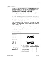
DMX Control Mode 

Operating in a DMX Control mode environment gives the user the greatest flexibility when it comes to 

customizing or creating a show.  In this mode you will be able to control each individual trait of the 

fixture and each fixture independently. The 

LEDrain™ 64 uses 7 channels of control. 

Note: DIP Switch 10 must be turned on to activate DMX control mode.  

Note: Older 8-DIP Switch version must have DIP Switch 8 turned off to activate DMX control 

mode. DIP Switches 1-7 set the DMX address, and the maximum address is 127. 

S e t t i n g   t h e   D M X  a d d r e s s  

This DMX mode enables the use of a universal DMX controller device. Each fixture requires a "start 

address" from 1 to 511. A fixture requiring one or more channels for control begins to read the data 

on the channel indicated by the start address. For example, a fixture that occupies or uses 7 channels 

of DMX and was addressed to start on DMX channel 100, would read data from channels: 100, 101, 

102, 103, 104, 105 and 106. Choose start addresses so that the channels used do not overlap and 

notate the start address selected for future reference.  

If this is your first time addressing a fixture using the DMX-512 control protocol than I suggest jumping 

to the Appendix Section and read th

e heading “DMX Primer”. It contains very useful information that 

will help you understand its use.  

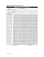
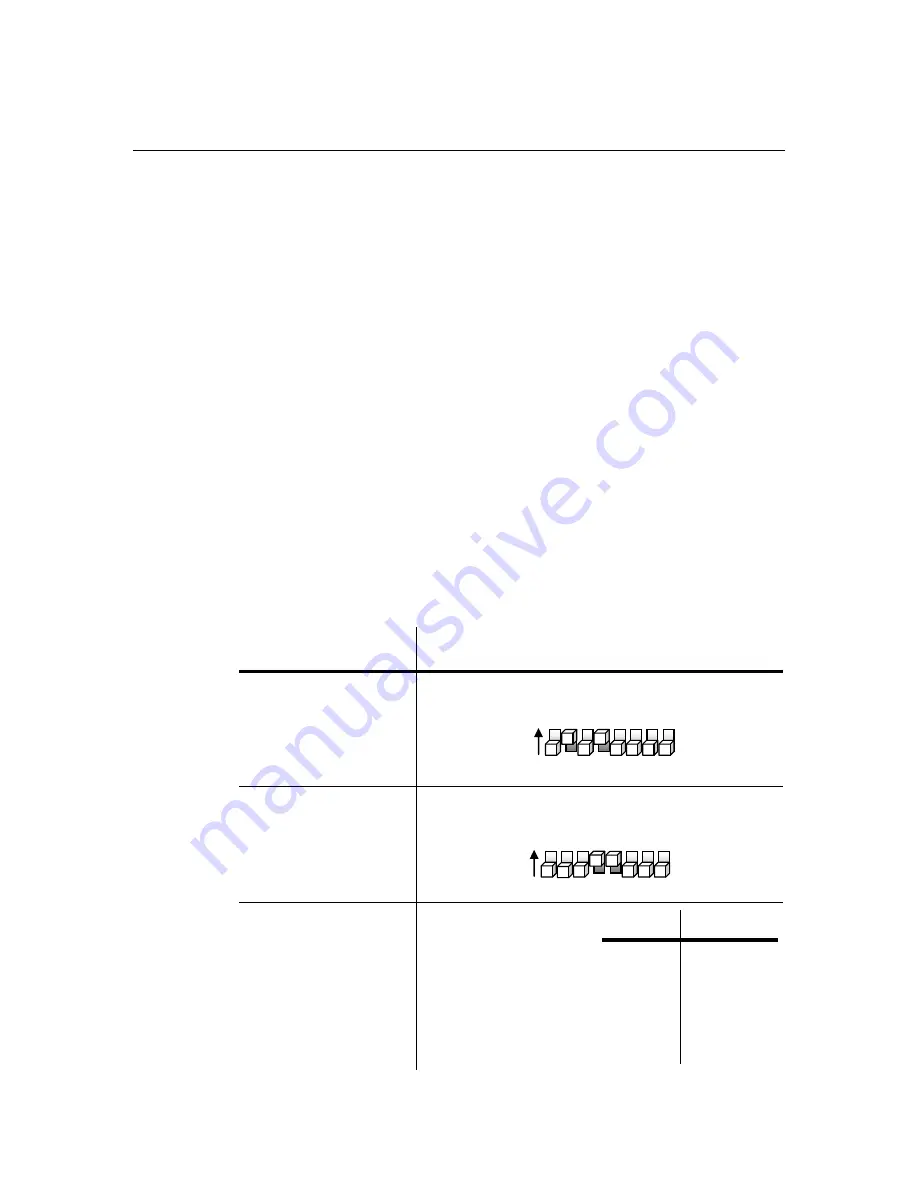
Set the start address using the group of DIP switches located usually on bottom of the fixture. Each 

dip switch has an associated value. Adding the value of each switch in the ON position will provide 

the start address. Determining which switches to toggle ON given a specific start address can be 

accomplished in the following manner. By subtracting the largest switch value possible from the 

selected start address until zero is achieved. 

E

XAMPLE 

S

TARTING 

A

DDRESS


Address 10 

Pin # 4 

= 8 

Pin # 2 

= 2 

Total  

= 10 


Address 24 

Pin # 5 

= 16 

Pin # 4 

= 8 

Total 

= 24 


Resolving address using  

simple math. 

Address 233


233 

– (128) = 105, Turn ON Dip # 8 

105 

– (64) = 41, Turn ON Dip # 7 

41 

– (32) = 9, Turn ON Dip # 6 

– (8) = 1, Turn ON Dip # 4 

– (1) = 0, Turn ON Dip # 1 


You will most likely use the first 

available number which maybe 

number 1. This number was 

selected for example purposes.  


D

IP 

S

WITCH


(DMX


V

ALUE


16 
32 
64 

128 


 1  2  3  4  5  6  7  8   

ON 

1


2


4


8


16


32


64


128


 1  2  3  4  5  6  7  8   

ON 

1


2


4


8


16


32


64


128


Summary of Contents for LEDrain 64

Page 1: ...S A 800 762 1084 954 929 1115 FAX 954 929 5560 www chauvetlighting com 2009 12 08 16 35 LEDrain 64 Snapshot Use on Dimmer Outdoor Use Sound Activated Master Slave DMX 100 240 VAC 50 60 Hz Replaceable...

Page 2: ...PRODUCT OVERVIEW 5 SETUP 6 POWER 6 MOUNTING 6 OPERATING INSTRUCTIONS 7 MASTER SLAVE MODE 7 Daisy Chain Connection 7 Dipswitch Options 7 DMX CONTROL MODE 8 Setting the DMX address 8 APPENDIX 9 DMX PRIM...

Page 3: ...that they also receive this instruction booklet Always make sure that you are connecting to the proper voltage and that the line voltage you are connecting to is not higher than that stated on decal...

Page 4: ...robe Selector switch for sound active or automatic mode Static colors and RGB color mixing in master slave mode via dip switches ADDITIONAL FEATURES Additional power output max 50 units 120 V 115 V mo...

Page 5: ...n LED Status ON signifies the par can is set to be controlled via DMX OFF Par can is set to either Automatic or Sound Active mode as previously selected by the Music Auto switch Hanging yoke also floo...

Page 6: ...rent draw under normal conditions All fixtures must be powered directly off a switched circuit and cannot be run off a rheostat variable resistor or dimmer circuit even if the rheostat or dimmer chann...

Page 7: ...Auto switch to Music and for sound activated triggering of the program Set Music Auto switch to Auto then use the rotary dial to adjust speed of the program See below under DIP Switch Options for add...

Page 8: ...d do not overlap and notate the start address selected for future reference If this is your first time addressing a fixture using the DMX 512 control protocol than I suggest jumping to the Appendix Se...

Page 9: ...sy Chain A Daisy Chain connection is where the DATA OUT of one fixture connects to the DATA IN of the next fixture The order in which the fixtures are connected is not important and has no effect on h...

Page 10: ...n 100 Blue 40 Red Green 100 Blue 60 Red Green 100 Blue 80 Red Green 100 Blue 100 Red Green Blue 100 Red 20 Green Blue 100 Red 40 Green Blue 100 Red 60 Green Blue 100 Red 80 Green Blue 100 Red 100 Gree...

Page 11: ...ping damage resulting from inadequate packaging is the customer s responsibility CHAUVET reserves the right to use its own discretion to repair or replace product s As a suggestion proper UPS packing...

Page 12: ...332 364 396 428 460 492 1 0 1 1 0 13 45 77 109 141 173 205 237 269 301 333 365 397 429 461 493 0 1 1 1 0 14 46 78 110 142 174 206 238 270 302 334 366 398 430 462 494 1 1 1 1 0 15 47 79 111 143 175 207...

Page 13: ...lluminance 1 m 3 142 lux Beam Angle 16 Field Angle 26 Photometric chart See page 11 FUSE Main 20 mm Glass 2 A Fast Blow CONTROL PROGRAMMING Data input locking 3 pin XLR male socket Data output locking...

Reviews: