background image


D I P S W I T C H   O P T I O N S  

F

UNCTIONS


D

IPSWITCHES 

(


ON


) N

OTES 

&


D

ESCRIPTION


Color change  
program 

None 

Music/Auto switch


Music: Sound Activated, Rotary knob sets sound sensitivity
Auto: Rotary knob sets speed of program 

1 Low 

Intensity 

2 Medium 

Intensity 

Red LEDs 

3 Full 

Intensity 

4 Low 

Intensity 

5 Medium 

Intensity 

Green LEDs 

6 Full 

Intensity 

7 Low 

Intensity 

8 Medium 

Intensity 

Blue LEDs 

9 Full 

Intensity 

“User Color” 

Any combination of Red, Green and 
Blue LED intensity to create custom 
color.  

For example Dipswitch 9 and 3 ON creates a Pink color 


DMX Mode 

This mode allows the unit to be controlled by any universal DMX controller. If you are unfamiliar with 

DMX, please read the DMX Primer on page 15.  

1) 

A working DMX-512 signal source plugged into the LEDsplash™ 2 activates the DMX mode. 


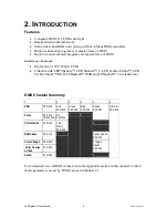
DMX Channel Values 

NOTE! 

Please read all instructions carefully on fixture DMX control mode and addressing.  

DMX channels 2, 3, 4, 5 and 6 functions are determined by the current settings of channel 1. For 

example, while Channel 1 is set between 000 and 029 the following conditions will apply; 

i. 

Channel 2 will control the Red LEDs


ii. 

Channel 3 will control the Green LEDs 

iii. 

Channel 4 will control the Blue LEDs 

iv. 

Channel 5 will control Strobing 

v. 

Channel 6 will control the Dimmer 


LEDsplash 2 User Manual 

11 

2008-01-22/09:14


Summary of Contents for LEDsplash 2

Page 1: ...Activated DMX512 Master Slave Autoswitching Transformer Replaceable Fuse User Serviceable Duty Cycle LEDsplash 2 USER MANUAL Chauvet 3000 N 29th Ct Hollywood FL 33020 U S A 800 762 1084 954 929 1115 F...

Page 2: ...n Conversion Chart 8 SETTING UP A DMX SERIAL DATA LINK 8 MASTER SLAVE FIXTURE LINKING 9 MOUNTING 9 Orientation 9 Rigging 9 4 OPERATING INSTRUCTIONS 10 OPERATION 10 Stand Alone Mode Sound Active Auto M...

Page 3: ...ching power supply that can accommodate a wide range of input voltages The only thing necessary to do before powering on the unit is to make sure the line voltage you are applying is within the range...

Page 4: ...acing fuse and be sure to replace with same fuse size and type Secure fixture to fastening device using a safety chain Never carry the fixture solely by its head Use its carrying handles Maximum ambie...

Page 5: ...e LED Techno Strobe RGB LEDsplash 200B and LEDsplash 2 in stand alone DMX Channel Summary 1 2 3 4 5 6 RGB 000 029 Red 000 255 Green 000 255 Blue 000 255 Pulse 030 119 Slow Fast No Function Strobe 000...

Page 6: ...acket Sound Sensitivity Knob Music Auto Switch Microphone Dipswitches Power Connector and Fuse Holder DMX Output Connector Power Output max 8 units LEDsplash 2 only DMX Input Connector LEDSplash 2 Use...

Page 7: ...y isolated splitter may result in deterioration of the digital DMX signal Maximum recommended serial data link distance 500 meters 1640 ft Maximum recommended number of fixtures on a serial data link...

Page 8: ...pin adapter CHAUVET Model No DMX5M or DMX5F The chart below details a proper cable conversion 3 PIN TO 5 PIN CONVERSION CHART Conductor 3 Pin Female output 5 Pin Male Input Ground Shield Pin 1 Pin 1...

Page 9: ...slave setting Please consult the Operating Instructions section in this manual for complete instructions for this type of setup and configuration Mounting ORIENTATION This fixture may be mounted in an...

Page 10: ...he Master Slave mode will allow you to link up to as many units you want in a daisy chain fashion In this mode the first unit in the daisy chain will automatically command all other units following 1...

Page 11: ...de allows the unit to be controlled by any universal DMX controller If you are unfamiliar with DMX please read the DMX Primer on page 15 1 A working DMX 512 signal source plugged into the LEDsplash 2...

Page 12: ...016 Red 017 056 Red Full Green 0 100 057 094 Green Full Red 100 0 095 096 Green 097 136 Green Full Blue 0 100 137 174 Blue Full Green 100 0 175 176 Blue 177 216 Blue Full Red 0 100 Color Macro Ch 1 12...

Page 13: ...its life 9 Light will not come on after power failure Some discharge lamps require a cooling off period before the electronics in the fixture can kick start it again wait 5 to 10 minutes before poweri...

Page 14: ...fixtures whose starting address is set incorrectly You can however control multiple fixtures of the same type using the same starting address as long as the intended result is that of unison movement...

Page 15: ...y 20 days Clean the internal optics at least every 30 60 days Returns Procedure Returned merchandise must be sent prepaid and in the original packing call tags will not be issued Package must be clear...

Page 16: ...ing Inrush Power 1 4A Power Factor 0 63 LIGHT SOURCE LED 24 8 red 8 green 8 blue 50 000hrs PHOTO OPTIC Beam Angle 11 8 Field Angle 22 Illuminance at 1m 5 627 lux THERMAL Maximum ambient temperature 10...

Reviews: