background image

C A B L E   C O N N E C T O R S  

This drawing provides a 
general illustration of the 
DMX Input/Output panel of 
a lighting fixture.  

U

X Controller


niversal DM

Continue the link 

Cabling must have a male XLR connector on one end and a female XLR connector on the other end. 

can cause a ground loop, and your fixture may perform erratically. Test cables with an ohm meter to 

r. 

3 - P I N   T O   5 - P I N   C O N V E

 pin DMX output connector, you will need to use a 5 pin to 3 pin adapter. 

CHAUVET Model No: DMX5M, or DMX5F. 

3


P

IN TO 

5


P

IN 

C

duc

3 Pin Female (output) 

5 Pin Male (Input) 

COMMON

DMX +

DMX

-

INPUT


OUTPUT

1


3


2


1

3

2

1

3

2

Resistance 120 
ohm 1/4w between 
pin 2 (DMX -) and 
pin 3 (DMX +) of 
the last fixture. 

Termination reduces signal errors. To 
avoid signal transmission problems 
and interference, it is always 
advisable to connect a DMX signal 
terminator.

DMX connector configuration 

CAUTION 

Do not allow contact between the common and the fixture’s chassis ground. Grounding the common 

verify correct polarity and to make sure the pins are not grounded or shorted to the shield or each othe

R S I O N   C H A R T  

Note!


If you use a controller with a 5

The chart below details a proper cable conversion: 

ONVERSION 

C

HART


Con

tor 

Ground/Shield 

Pin 1 

Pin 1 

Data ( - ) signal 

Pin 2 

Pin 2 

Data ( + ) signal 

Pin 3 

Pin 3 

Do not use 


Do not use 

Do not use 


Do not use 

Setting up a DMX Serial Data Link  

e of 
 pin 

2. 

a (female) 3 

3. 

ove to the input of the following 

escription 

.5m/14.8ft 


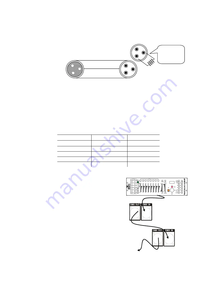
1.  Connect the (male) 3 pin connector sid

the DMX cable to the output (female) 3
connector of the controller.   

Connect the end of the cable coming from 
the controller which will have 
pin connector to the input connector of the 
next fixture consisting of a (male) 3 pin 
connector.  

Then, proceed to connect from the outpu
as stated ab
fixture and so on. 

CHAUVET Certified DMX Data Cables 

Order Code 

D

DMX1.5   

DMX Cable 1.5m/4.9ft 

DMX4.5   

DMX Cable 4

DMX10 


DMX Cable 10m/32.8ft 

MiNWash 8 

2007-09-14/09:44


Summary of Contents for MiN Wash

Page 1: ...Sound Activated DMX512 Master Slave 115V 230V Switch Replaceable Fuse User Serviceable Duty Cycle MinWash USER MANUAL Chauvet 3000 N 29th Ct Hollywood FL 33020 U S A 800 762 1084 954 929 1115 FAX 954...

Page 2: ...ROL PANEL 10 MENU MAP 11 USER CONFIGURATIONS 12 To set the pan to inverting or non inverting 12 To set the tilt to inverting or non inverting 12 To set the LED Readout to Inverting or Non Inverting 12...

Page 3: ...verage current draw under normal conditions All fixtures must be powered directly off a switched circuit and cannot be run off a rheostat variable resistor or dimmer circuit even if the rheostat or di...

Page 4: ...rce before servicing or replacing fuse and be sure to replace with same size and type of fuse Secure fixture to fastening device using a safety chain Never carry the fixture solely by its head Use its...

Page 5: ...r selectable basic or advanced operating modes User selectable pan tilt ranges Pan 540 360 180 Tilt 270 180 90 Compact and lightweight LED display with on off auto settings Reset to factory settings o...

Page 6: ...FUNCTION 1 Pan 2 Tilt 3 Shutter 4 Color Macro 5 Reserved Product Overview Lens Projector Head CA 9 Controller Input LED Readout Voltage Selector Switch DMX Out IEC Power Connection w fuse holder DMX I...

Page 7: ...data link Connecting more than 32 fixtures on one serial data link without the use of a DMX optically isolated splitter may result in deterioration of the digital DMX signal Maximum recommended seria...

Page 8: ...not allow contact between the common and the fixture s chassis ground Grounding the common verify correct polarity and to make sure the pins are not grounded or shorted to the shield or each othe RSI...

Page 9: ...a male 3 pin connector Then ounting RIENTATION This fixture may be mounted in any position provided there is adequate room for ventilation RIGGING It is important never to obstruct the fan or vents pa...

Page 10: ...ER DOWN UP MODE ESC The Control Panel LED Display shows the menu items you select from the menu map on page 11 When a menu function is selected the display will show immediately the first available op...

Page 11: ...Menu Map MinWash 11 2007 09 14 09 44...

Page 12: ...CHANNEL CONFIGURATION 1 Press the Mode button until it shows or 2 Use the Up Down buttons to set to the desired inversion press enter to confirm TO SET THE MAXIMUM PAN ANGLE 1 Press the Mode button un...

Page 13: ...ture For more information about terminators see page 8 2 Choose a unit to function as the Master Select NAFA NASL or NStS see below for readout depending upon which master mode you require The master...

Page 14: ...ction Magenta Purple Orange Pink Yellow Pale Green Light Blue Teal Sky Blue Blue Olive Turquoise Orange Yellow Magenta White Color Change Macro 1 Color Change Macro 2 Color Change Macro 3 Color Change...

Page 15: ...5 056 067 068 079 080 091 092 103 104 115 116 127 128 139 140 151 152 163 164 175 176 187 188 199 200 212 213 225 226 239 240 255 Color Macros No Function Magenta Purple Orange Pink Yellow Pale Green...

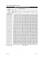
Page 16: ...he largest value switch that is less than the start address Turn this switch on 2 Subtract the value of the switch you just turned on from the starting address number 3 Determine the largest value swi...

Page 17: ...7 109 141 173 205 237 269 301 333 365 397 429 461 493 0 1 1 1 0 14 46 78 110 142 174 206 238 270 302 334 366 398 430 462 494 1 1 1 1 0 15 47 79 111 143 175 207 239 271 303 335 367 399 431 463 495 0 0...

Page 18: ...of its life 9 Light will not come on after power failure Some discharge lamps require a cooling off period before the electronics in the fixture can kick start it again wait 5 to 10 minutes before po...

Page 19: ...of the fixtures whose starting address is set incorrectly You can however control multiple fixtures of the same type using the same starting address as long as the intended result is that of unison m...

Page 20: ...y Clean the external optics at least every 20 days Clean the internal optics at least every 30 60 days Returns Procedure Returned merchandise must be sent prepaid and in the original packing call tags...

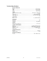
Page 21: ...LIGHT SOURCE LED 1 14W RGB 50 000hrs PHOTO OPTIC Beam Angle 27 Field Angle 53 Illuminance 64fc 689 lux THERMAL Maximum ambient temperature 104 F 40 C CONTROL PROGRAMMING Data input locking 3 pin XLR...

Reviews: