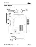
Setup
April 8, 2010
9
SparkliteLED™ User Manual - Rev. 02c
Fixture Linking
The SparkliteLED™ controller can operate in any of two modes, 12-channel or 24-
channel. In both cases, the SparkliteLED™ controller links to a DMX controller and t
other DMX compatible fixtures using DMX links. However, it is important to pay
attention to the connection method for each of these modes.
If you are not familiar with the DMX standard, please refer to the Appendix
chapter to learn more about it.
DMX Data
Connection
The SparkliteLED™ uses the standard DMX data connection for its DMX 24-
Channel mode. See the Introduction chapter for a description of the DMX 24-
Channel mode and the Operation Instructions chapter to learn how to configure the
SparkliteLED™ controller appropriately for this mode.
Procedure
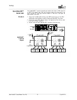
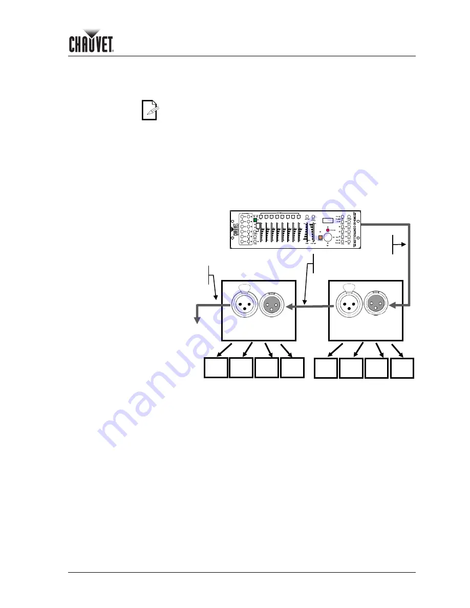
1. Connect the first DMX cable to between the DMX Output connector of the DMX
controller and the DMX Input connector of the first SparkliteLED™ controller.
2. Connect the second DMX cable as shown in the figure below.
3. Continue linking the other SparkliteLED™ controllers in the same way.
DMX Data
Connection
Diagram
2
nd
SparkliteLED™
1
st
SparkliteLED™
DMX
Output
DMX
Input
DMX
Input
DMX
Output
Universal
DMX
Controller
1
st
DMX
Cable
2
nd
DMX
Cable
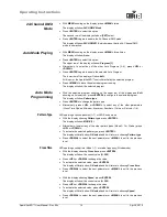
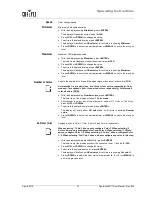
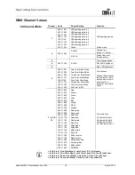
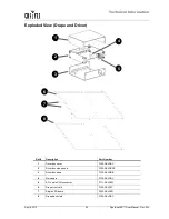
Drape
1
Drape
2
Drape
3
Drape
4
Drape
1
Drape
2
Drape
3
Drape
4
3
rd
DMX
Cable
Next
SparkliteLED™
Summary of Contents for Sparklite LED
Page 1: ...User Manual...


