Setup
SparkliteLED™ User Manual - Rev. 02c
10
April 8, 2010
SparkliteLED™
Serial Link
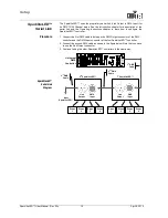
The SparkliteLED™ uses the proprietary serial link (Link Output to DMX Input) for
its DMX 12/24 Channel mode. See the
Introduction
chapter for a description of the
serial link and the
Operating Instructions
chapter to learn how to configure the
SparkliteLED™ controller.
Procedure
1. Connect the first DMX cable to between the DMX Output connector of the DMX
controller and the DMX Input connector of the first SparkliteLED™ controller.
2. Connect the second DMX cable as shown in the figure below. Note that you have
to use the Link Output connector.
3. Continue linking the other SparkliteLED™ controllers in the same way.
SparkliteLED™
Serial Link
Diagram
2
nd
SparkliteLED™
1
st
SparkliteLED™
Link
Output
DMX
Input
DMX
Input
Link
Output
Universal
DMX
Controller
1
st
DMX
Cable
2
nd
DMX
Cable
Drape
1
Drape
2
Drape
3
Drape
4
Drape
1
Drape
2
Drape
3
Drape
4
3
rd
DMX
Cable
Next
SparkliteLED™
Summary of Contents for Sparklite LED
Page 1: ...User Manual...


