background image

Appendix 


April 8, 2010 

29 

SparkliteLED™ User Manual - Rev. 01d 

DMX Connectivity (Cont.)


The figure below is only an example of a possible DMX serial connection.  


Generic DMX Data 

Connection Diagram 


Master/Slave 

Linking 


The Master/Slave mode allows one fixture (the master) to run a preconfigured program 
to control several other fixtures of the same model (the slaves) without requiring a DMX 
controller. In this mode, all the slave fixtures will operate in unison  with the master 
fixture. 

If a fixture supports the Master/Slave mode, it will have some sort of programming 
function to configure it as master or slave. Those fixtures that only support DMX mode 
cannot operate in Master/Slave mode. 


Master/Slave 

Connection  


Make sure the fixtures with which you are working are capable of operating in 
Master/Slave mode. When working in Master/Slave mode, most fixtures use the DMX 
data connection as well. The difference in this case is that there is no DMX controller 
involved.  Refer to the fixtures’ manual to learn how to configure them to work in 
Master/Slave mode.  

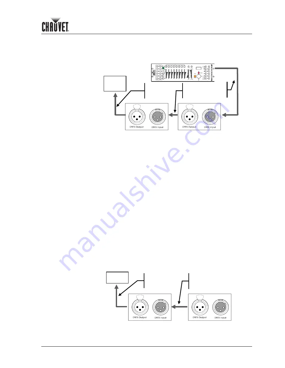
The procedure below illustrates a possible connection method. 


1)  Connect the 3-pin, male connector of the first DMX cable to the DMX Output 

connector (3-pin, female) of the master fixture. 

2)  Connect the 3-pin, female connector of the first DMX cable coming from the master 

fixture to the DMX Input connector (3-pin, male) of the first slave fixture.  

3)  Connect the 3-pin, male connector of the second DMX cable to the DMX Output 

connector (3-pin, female) of the first slave fixture. 

4)  Connect the 3-pin, female connector of the second DMX cable coming from the first 

slave fixture to the DMX Input connector (3-pin, male) of the second slave fixture. 

5)  Continue linking the other slave fixtures in the same way. 

6)   Follow the steps in fixtures’ manual to configure the fixtures as master and slaves. 


Generic Master/Slave 

Connection Diagram 


2

nd

 DMX Fixture 

1

st

 DMX Fixture 

Other DMX 

Compatible 

Fixtures 

First 

DMX 

Cable 

Second 
DMX 
Cable 

Third 
DMX 
Cable 

DMX 

Controlle


Other Slave 

Fixtures 

First Slave Fixture 

Master Fixture 

First 
DMX 
Cable 

Second 
DMX 
Cable 

Summary of Contents for Sparklite LED

Page 1: ...User Manual...

Page 2: ...5 x 11 inches double sided If using A4 paper 210 x 297 mm configure your printer to scale the content of this document to A4 paper Intended Audience Any person in charge of installing operating and or...

Page 3: ...8 AC POWER 8 Fuse Replacement 8 Power Linking 8 FIXTURE LINKING 9 DMX Data Connection 9 SparkliteLED Serial Link 10 Master Slave Fixture Linking 11 MOUNTING 12 Orientation 12 Rigging 12 SparkliteLED C...

Page 4: ...27 Number of Fixtures 27 DMX Data Cabling 27 Making your Own DMX Cable 27 DMX Cable Characteristics 27 DMX Cable Connectors 28 3 Pin to 5 Pin Conversion Chart 28 DMX Connection 28 MASTER SLAVE LINKING...

Page 5: ...it in its original factory box or road case and packing Text Conventions CONVENTION MEANING 1 512 A range of values 50 60 A set of mutually exclusive values in the text 10 A DIP switch to be configure...

Page 6: ...controller to the proper voltage as per the specifications in this manual or on the controller Always disconnect the SparkliteLED controller and drape s from the power source before servicing This pro...

Page 7: ...t groups of 16 RGB LEDs each with a total of 128 LEDs per drape Despite having individual outputs for each drape all four SparkliteLED drapes connected to the same SparkliteLED controller will show th...

Page 8: ...ore information on these types of connections If using the standard DMX connection each SparkliteLED controller can have its own starting address for a more detailed control of the show see the Append...

Page 9: ...1 8 12 Drape s On Off 24 Channel Mode CHANNEL FUNCTION 1 1st Group Red Color 2 1st Group Green Color 3 1st Group Blue Color 4 2nd Group Red Color 5 2nd Group Green Color 6 2nd Group Blue Color 7 3rd G...

Page 10: ...iteLED User Manual Rev 02c 6 April 8 2010 Product Dimensions SparkliteLED Controller Fuse Holder Power Input DMX In DMX Out On Off Switch Link Out Power Indicator Control Panel Drape Out Connectors DM...

Page 11: ...Introduction April 8 2010 7 SparkliteLED User Manual Rev 02c SparkliteLED Drape SparkliteLED Driver Box LED Group Outputs Mounting Grommet LEDs...

Page 12: ...Breakers section in the Appendix chapter Never connect the fixture to a rheostat variable resistor or dimmer circuit even if the rheostat or dimmer channel serves only as a 0 to 100 switch Fuse Replac...

Page 13: ...4 Channel mode See the Introduction chapter for a description of the DMX 24 Channel mode and the Operation Instructions chapter to learn how to configure the SparkliteLED controller appropriately for...

Page 14: ...MX cable to between the DMX Output connector of the DMX controller and the DMX Input connector of the first SparkliteLED controller 2 Connect the second DMX cable as shown in the figure below Note tha...

Page 15: ...son The SparkliteLED uses the serial link Link Output to DMX Input for its Master Slave mode as well 1 Link the fixtures as indicated in steps 3 to 5 of the previous section 2 Make sure that there is...

Page 16: ...l for the weight requirement of this fixture SparkliteLED Controller You should mount the SparkliteLED controller on a flat dry and rigid surface such as plywood or similar The SparkliteLED controller...

Page 17: ...able options for the current menu item To move to the left side of the menu map previous level press MENU This will return the display to the previous option or exit the current option without changin...

Page 18: ...change the pattern type Alternatively press UP or DOWN to select any of the other parameters Cross Time Speed Minimum Maximum Number of Colors or Set color 1 4 Pattern Type LED sparking direction pat...

Page 19: ...hree or two colors respectively Color mode 8 is for all colors RGB With the display showing Number colors press ENTER The lower row of the display will show 1 Color mode Alternatively to select any of...

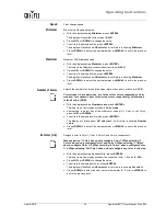
Page 20: ...the display press MENU five times The display will show Settings Press ENTER The display will show SET DMX address Alternatively to select the other setting Allow edit PROG press UP or DOWN Starting...

Page 21: ...e Activates the LED strobe mode Cross time 0 255 LED spark duration or strobe frequency Speed Color change speed when in Strobe Minimum Minimum LED brightness Maximum Maximum LED brightness Number col...

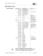
Page 22: ...ree Color Flow Mode Two Color Flow Mode Full Color RGB Color Modes Channel 6 determines the number of colors and the way they will show static or dynamic or all RGB colors 7 8 9 10 000 009 010 019 020...

Page 23: ...d Color RGB Color Control per LED group 2 000 255 1st Group Green Color 3 000 255 1st Group Blue Color 4 000 255 2nd Group Red Color 5 000 255 2nd Group Green Color 6 000 255 2nd Group Blue Color 7 00...

Page 24: ...below recommendations Unplug the fixture from power Wait until the fixture is cold Use a vacuum or dry compressed air and a soft brush to remove dust collected on the external vents and reachable inte...

Page 25: ...troller not powered Check power to the SparkliteLED controller Faulty DMX cable Repair or replace faulty cable Breaker Fuse keeps blowing Excessive circuit load Check total load placed on the electric...

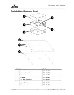
Page 26: ...IECMALE 5 On Off switch P100 SA00013 6 3 Pin XLR male socket DMX Input P111 SKLX3M 7 11 3 Pin XLR female socket DMX Out Link Out P111 SKLX3F 8 Display board P170 SKLDPLY 9 Main board P170 SKLMAS 10 5...

Page 27: ...Ref Description Part Number 1 Driver box cover P100 SKLDBC 2 Driver box side panels P100 SKLDBSP 3 Driver box base P100 SKLDBB 4 Main board P170 SKLDRV 5 5 Pin male XLR connector P111 SKLX5M 6 Drape...

Page 28: ...g from inadequate packaging is the customer s responsibility As a suggestion proper UPS packing or double boxing is always a safe method to use CHAUVET reserves the right to use its own discretion to...

Page 29: ...n inside power supply Maximum operating temperature 104 F 40 C Drape Fire Resistance Treatment Fire retardant type FR 1 non toxic Fire retardant duration 10 dry cleaning procedures Standard compliance...

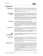
Page 30: ...ue in the 000 255 range Each DMX compatible fixture uses as many consecutive DMX channels as features the user can control The sequential numbers assigned to each DMX channel 1 512 are also known as D...

Page 31: ...roller communicates to each fixture However the user should always define a physical location for the fixtures that provides for the easiest and most direct cabling to the controller and other fixture...

Page 32: ...signal Pin 2 Pin 2 Positive signal Pin 3 Pin 3 Not Used Pin 4 Not Used Pin 5 DMX Connection Make sure that the fixtures with which you are working can operate in DMX mode not in a proprietary connect...

Page 33: ...ontroller involved Refer to the fixtures manual to learn how to configure them to work in Master Slave mode The procedure below illustrates a possible connection method 1 Connect the 3 pin male connec...

Page 34: ...user to control simultaneously the whole group of units at that DMX address by setting the ID Addressing channel to 0 Similarly the user can control each fixture at that DMX address independently by f...

Page 35: ...t as the PF decreases the difference between the current calculated using the watts volts method and the actual current increases Therefore for fixtures with a PF below 0 9 the installer must always c...

Page 36: ...CHAUVET 3000 N 29th Ct Hollywood FL 33020 U S A 800 762 1084 954 929 1115 FAX 954 929 5560 www chauvetlighting com SparkliteLED User Manual Rev 02c April 2010...

Reviews: