background image


TriShot™ LED User Manual (Rev. 01a) 

Page 15 of 18 

DMX Primer 


The USITT DMX512-A data transmission protocol (DMX, from now on) is based on 
the EIA-485 standard and it has 512 channels (001 to 512). This system requires a 
controller (DMX controller), one or more DMX compatible fixtures, and a DMX circuit 
(also known as “DMX universe”) to link the fixtures to the controller. 

Depending on their complexity and features, DMX compatible fixtures may require 
from one to more than 30 DMX channels to operate. Some DMX fixtures have 
multiple operation modes (also known as “personalities”), each with its own number 
of channels and controllable parameters. 


Starting Address 


In the DMX system, the controller sends DMX data to each fixture based on the 
fixture’s starting address. The starting address is the number of the DMX channel 
(001 to 512) assigned to the fixture’s first control channel (Channel 1). When 
assigning starting addresses to multiple fixtures, it is critical to ensure that no starting 
address is already in use by another fixture to prevent channels from overlapping. 
Otherwise, the affected fixtures may operate erratically. 

For instance, a user has two DMX compatible fixtures. Fixture “A” has four channels 
and fixture “B” has six channels. If the user configures the starting address of fixture 
“A” to “001”, channels 001 through 004 on the DMX controller will control fixture “A”. 
This means that the user should assign the starting address of fixture “B” to “005” or 
higher. For a starting address of “005”, the DMX controller would use channels 005 to 
010 to control fixture “B”.  

It is possible to control multiple fixtures of the same type by assigning each one of 
them the same starting address. In this case, all the fixtures would respond in unison 
(synchronized) to the signals from the DMX controller.


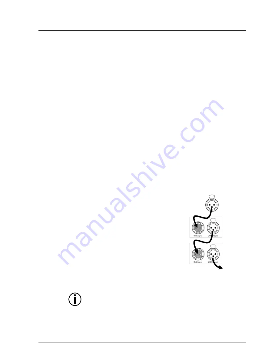
Fixture Linking (Daisy Chain) 


DMX compatible fixtures receive the control signals 
from the DMX controller through the DMX cables. 
Each fixture has a DMX In and a DMX Out 
connector. The figure to the right illustrates how the 
fixtures link to each other using multiple segments of 
DMX cable in a sequential format called “daisy 
chain”.  

The order in which the fixtures connect to the DMX 
controller is irrelevant because all fixtures receive 
the same DMX signals and they only respond to 
them based on their individual starting addresses. 
However, it is important to notice that the 
connections between fixtures should always be as 
short and direct as possible.  

To ensure the integrity of the DMX signal, follow the 
recommendations of the EIA-485 standard: 


  The maximum recommended cable length is 500 m (1,640 feet). 

  The maximum recommended number of fixtures on the same daisy chain is 32. 


Connecting more than 32 fixtures on one daisy chain without the use of a DMX 
optically-isolated splitter may result in deterioration of the digital DMX signal. 


DMX


Controller

1

st


DMX


Fixture

2

nd


DMX


Fixture

To


other


fixtures

Summary of Contents for TriShot LED

Page 1: ...User Manual ...

Page 2: ...mation 12 General Maintenance 12 General Troubleshooting 13 Returns Procedure 14 Claims 14 Contact Information 14 DMX Primer 15 6 Technical Specifications 18 Document Information The information and specifications contained in this document are subject to change without notice CHAUVET assumes no responsibility or liability for any errors or omissions that may appear in this manual Copyright 2011 C...

Page 3: ... A key to be pressed on the fixture s control panel 1 512 A range of values 50 60 A set of values of which only one can be chosen Settings A menu option not to be modified for example showing the operating mode current status Menu Settings A sequence of menu options to be followed ON A value to be entered or selected Icons Icon Meaning This paragraph contains critical installation configuration or...

Page 4: ...t no ventilation slots on the unit s housing are blocked Always disconnect this product from the power source before cleaning it or replacing the fuse Make sure to replace the fuse with another of the same type and rating If mounting this product overhead always secure it to a fastening device using a safety cable The maximum ambient temperature Ta is 104 F 40 C Do not operate this product at high...

Page 5: ...iShot LED User Manual Rev 01a Page 5 of 18 2 INTRODUCTION Product Overview Microphone Sensitivity DIP switches Fuseholder Power in hardwired Safety DMX in DMX out Focus adjustment Bracket adjustment knob ...

Page 6: ...Page 6 of 18 TriShot LED User Manual Rev 01a Product Dimensions ...

Page 7: ...of the fixture or refer to the fixture s specifications chart A fixture s listed current rating indicates its average current draw under normal conditions Always connect this product to a protected circuit circuit breaker or fuse making sure that it has an appropriate electrical ground to avoid the risk of electrocution or fire Never connect this product to a rheostat variable resistor or dimmer c...

Page 8: ... platform or a truss When rigging this product onto a truss you should use a mounting clamp of appropriate weight capacity The bracket has a 13 mm hole which is appropriate for this purpose When mounting this product overhead always use a safety cable Before deciding on a location for this product always make sure that it will be easy to access the unit for maintenance and programming purposes The...

Page 9: ...arting address Configuration Standalone Modes Set this product in one of the standalone modes to control it without a DMX controller 1 Connect this product to a suitable power outlet 2 Turn this product on Sound Active Mode To enable the Sound Active mode do the following 1 Set DIP switch 10 to the ON position 2 Turn the music on and adjust the microphone sensitivity knob until the fixture starts ...

Page 10: ...d the slave units will operate in unison with the master unit Configure the units as indicated below Slave units 1 Set DIP switch 2 10 to the OFF position 2 Set DIP switch 1 to the ON position 3 Connect the DMX input of the first slave unit to the DMX output of the master unit 4 Connect the DMX input of the subsequent slave units to the DMX output of the previous slave unit 5 Finish setting and co...

Page 11: ...255 Slow fast Strobe channels 1 4 only 000 015 016 255 No function Slow fast 6 18 Hz 6 Operating mode when CH 6 is set between 032 223 CH 5 controls the speed 000 031 032 063 064 095 096 127 128 159 160 191 192 223 224 255 RGB mode Pulse effect 0 100 using RGB faders Pulse effect 100 0 using RGB faders Pulse effect 100 0 100 using RGB faders Auto fade transition Auto snap transition 3 colors Auto ...

Page 12: ...quency To clean this fixture follow the instructions below Unplug the fixture from power Wait until the fixture is cold Use a vacuum or dry compressed air and a soft brush to remove dust collected on the external surface vents Clean all external optics and glass surfaces with a mild soap solution ammonia free glass cleaner or isopropyl alcohol Apply the solution directly to a soft lint free cotton...

Page 13: ... right fader s on the controller Wrong DMX personality on the fixture Set the correct DMX fixture s personality Assign the faders accordingly Wrong polarity setting on the DMX controller Change the signal polarity on the controller Loose or damaged DMX cable Check the DMX cable before the faulty unit Internal problem Send product for repair Intermittent DMX Problems Signal cables are not DMX compa...

Page 14: ...e right to use its own discretion to repair or replace returned product s Claims The carrier is responsible for any damage incurred during shipping to this product or any part that shipped with it Therefore if the received merchandise appears to have damages caused during shipping the customer must submit the damage report and any related claims with the carrier not CHAUVET The customer must submi...

Page 15: ...l control fixture A This means that the user should assign the starting address of fixture B to 005 or higher For a starting address of 005 the DMX controller would use channels 005 to 010 to control fixture B It is possible to control multiple fixtures of the same type by assigning each one of them the same starting address In this case all the fixtures would respond in unison synchronized to the...

Page 16: ...or on the other end The DMX protocol indicates that the XLR connectors must have five pins However most lighting fixtures use the 3 pin XLR connector The pin assignment of the 3 pin and 5 pin XLR connectors in a DMX cable is as follows Male Plug Female Plug Signal 3 Pin 5 Pin 5 Pin 3 Pin Signal Common 1 1 1 1 Common Data 2 2 2 2 Data Data 3 3 3 3 Data Not used 4 4 Not used Not used 5 5 Not used Yo...

Page 17: ...2 264 296 328 360 392 424 456 488 1 0 0 1 0 9 41 73 105 137 169 201 233 265 297 329 361 393 425 457 489 0 1 0 1 0 10 42 74 106 138 170 202 234 266 298 330 362 394 426 458 490 1 1 0 1 0 11 43 75 107 139 171 203 235 267 299 331 363 395 427 459 491 0 0 1 1 0 12 44 76 108 140 172 204 236 268 300 332 364 396 428 460 492 1 0 1 1 0 13 45 77 109 141 173 205 237 269 301 333 365 397 429 461 493 0 1 1 1 0 14...

Page 18: ...00 240 V 50 60 Hz Auto ranging Parameter 120 V 60 Hz 230 V 50 Hz Consumption 17 W 0 15 A 20 W 0 09 A Power I O Input Output Connectors IEC N A Cord plug Edison N A Light Source Type Power Lifespan LED 3 W 50 000 hours Color Quantity Current Tri color 1 350 mA Photo Optic Parameter Illuminance 1 m 1 592 lx Illuminance 2 m 305 lx Beam angle 11º Thermal Maximum External Temp Cooling System 104 F 40 C...

Reviews: