11
11
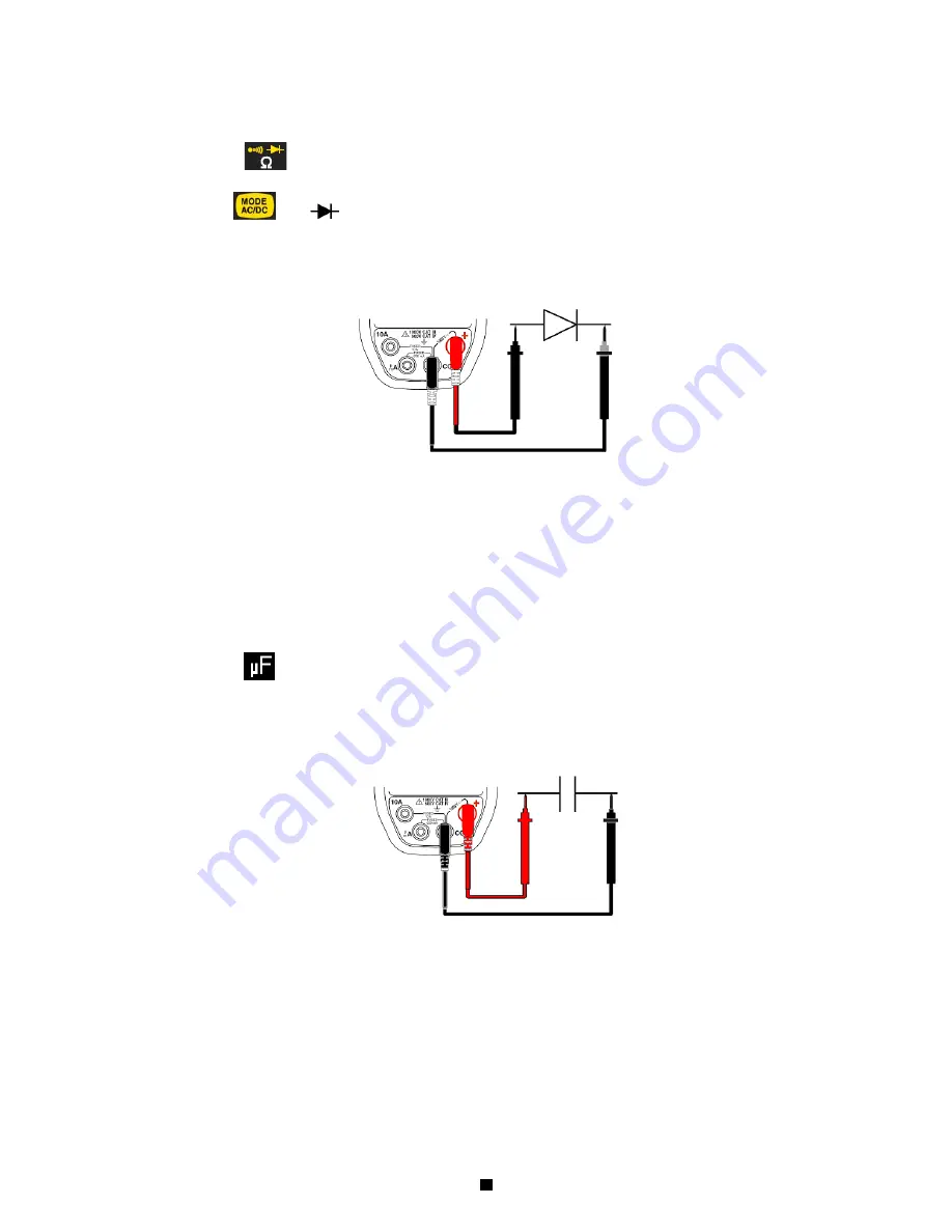
3.1.6 Diode test
To measure and check a semiconductor junction, proceed as follows:
1. Set the switch to
;
2. Press twice on
. The
symbol is displayed;
3. Connect the black lead to the
COM
terminal and the red lead to "
+
";
4. Place the test probes on the terminals of the component;
5. Read the junction threshold voltage measurement indicated on the display.
6. "
O.R
" is displayed if the circuit is open.
3.1.7 Capacitance measurement
To measure the capacitance, proceed as follows:
1. Set the switch to
;
2. Connect the black lead to the
COM
terminal and the red lead to "
+
";
3. Place the test probes on the terminals of the component;
4. Read the measurement indicated on the display.
"
O.L
" is displayed if the value to be measured exceeds the capacitance of the range or if the capacitor is short-circuited.
¾
For high values, the measurement cycle includes the display of "run" with a "rolling" decimal point. This indicates
that acquisition is in progress: wait for the display of the digital result.
¾
Prior discharge of very high capacitances helps to reduce the duration of the measurement.
3. NB: For greater accuracy, avoid subjecting the instrument to sudden temperature changes.


