20
3.5. 3P EARTH RESISTANCE MEASUREMENT
This function is the only one that can measure an earth resistance when the electrical installation to be tested is not live (new
installation, for example). It uses two additional rods, with the third rod being constituted by the earth electrode to be tested
(whence the name “3P”).
It can be used on an existing electrical installation, but the power must be cut off (main RCD). In all cases (new or existing instal-
lation), the earthing strip of the installation must be open during the measurement.
It is possible to make a rapid measurement and measure only R
E
or else to make a more detailed measurement by also measur-
ing the resistances of the rods.
3.5.1. DESCRIPTION OF THE MEASUREMENT PRINCIPLE
The device generates between the H and E terminals a square wave at a frequency of 128 Hz and an amplitude of 35 V. It meas-
ures the resulting current, I
HE
, along with the voltage present between the S and E terminals, U
SE
. It then calculates the value of
R
E
= U
SE
/I
HE
.
To measure the resistances of the R
S
and R
H
rods, the device internally reverses the E and S terminals and makes a measurement.
It then does likewise with the E and H terminals.
3.5.2. MAKING A MEASUREMENT
There are several measurement methods. We recommend the «62%» method.
SET UP
OFF
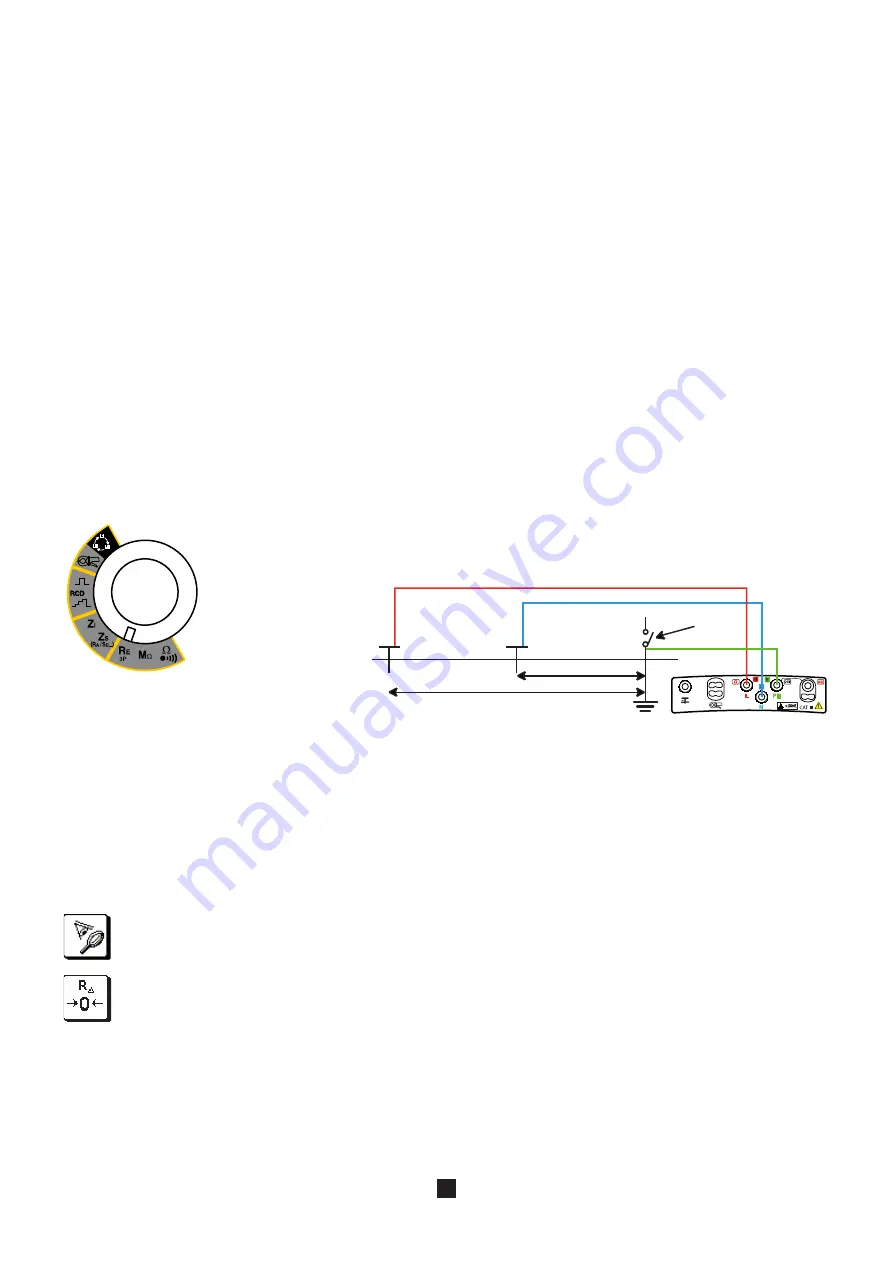
Connect the cables to the H and S terminals. Power down the installation and disconnect the earth strap. Then connect the E
terminal to the earth electrode to be checked.
The alarm, if activated, serves to inform the user, by an audible signal, that the measurement is above threshold, making it un-
necessary to look at the display unit to check this point.
3.5.3. CONFIGURING THE MEASUREMENT
Before starting the measurement, you can configure it by modifying the parameters displayed:
62% d
d
H
S
To compensate for the resistance of the lead connected to the E terminal, for measurements of low values (see §3.13).
Set the switch to RE 3P.
Plant the H and S rods in line with the earth electrode. The distance between the S rod
and the earth electrode must be approximately 62% of the distance between the H rod
and the earth electrode.
In order to avoid electromagnetic interference, we recommend paying out the full length of
the cables, placing them as far apart as possible, and not making loops.
Choice of type of measurement: rapid, to measure RE only (icon crossed out), or detailed, to measure also rod
resistances R
S
and R
H
. This last case is useful if the ground is dry, making the resistance of the rods high.
earth
strap


