46
3.11. CURRENT AND LEAKAGE CURRENT MEASUREMENT
This measurement requires the use of a specific optional current clamp.
It can measure very low currents (of the order of a few mA) like fault currents or leakage currents, and high currents (of the order
of a few hundred Amperes).
The C177 and MN77 clamps are better suited to the leakage current measurement because they are ten times as sensitive as
the C177A clamp.
3.11.1. DESCRIPTION OF THE MEASUREMENT PRINCIPLE
The specific clamps operate on the current transformer principle: the primary is constituted by the conductor in which the current is
to be measured, while the secondary is constituted by the internal winding of the clamp. This winding is itself closed through a resist-
ance having a very low value, located in the device. The voltage across the terminals of this resistance is measured by the device.
Two of the four points of connection of the clamp serve to identify the type of clamp (x 1,000 or x 10,000) and the other two to
measure the current. Knowing the ratio of the clamp, the device displays a direct reading of the current.
3.11.2. MAKING A MEASUREMENT
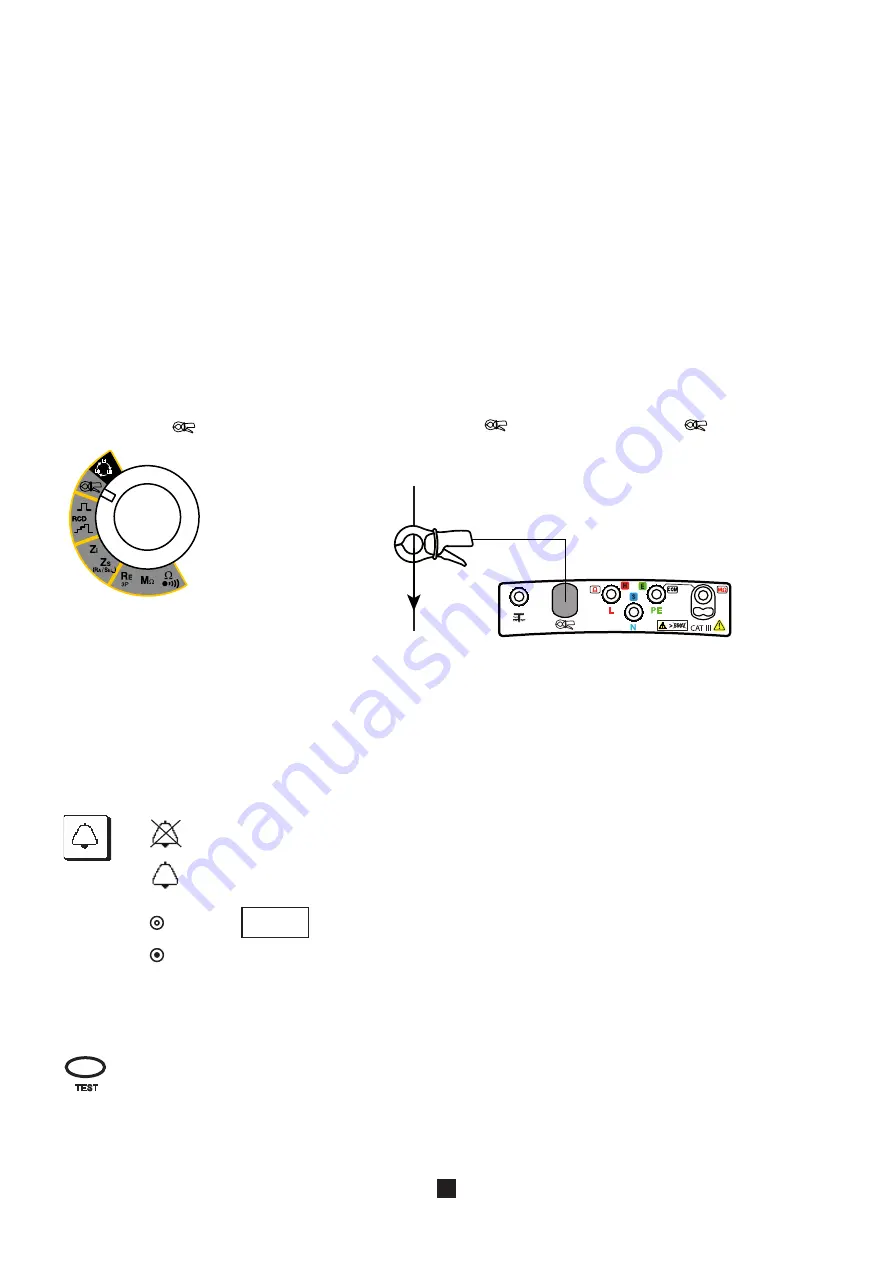
Set the switch to
.
Connect the clamp to the
terminal on the device. The
symbol is then dis-
played. Actuate the trigger to open the clamp and encircle the conductor to be meas-
ured. Release the trigger.
SET UP
OFF
The current measurement can be made on different conductors of an installation. This is why it has been made possible to index
the value recorded with one of the following values:
1, 2, 3, N, PE, or 3L (sum of the phase currents or phase and neutral currents, to measure the leakage current).
3.11.3. CONFIGURING THE MEASUREMENT
Before starting the measurement, you can program an alarm:
I
200.0
A
m A
TEST
To deactivate the alarm.
To activate the alarm.
To set the alarm threshold (see §3.14). As default, the threshold is set to 200 A.
Press the
TEST
button once to start the measurement and a second time to stop it.


