background image


3.4.5 

Default configuration 

To reset the clamp to its default parameters (factory configuration): 

In the OFF position, hold the


 key down while turning the switch to 

,


until the "full screen" display ends and a beep is emitted, to enter the 

configuration mode. The "rSt" symbol is displayed. 
 
After 2 s, the clamp emits a double beep, then all of the symbols of the 
screen are displayed until the 

 key is released. The default 

parameters are then restored: 

Continuity detection threshol

d =40Ω 

True Inrush triggering threshold =10% 
Temperature measurement unit =°C 


3.5 

VOLTAGE MEASUREMENT (V) 

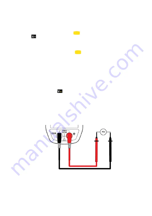
To measure a voltage, proceed as follows : 

1.  Set the switch to 

 ;  

2.  Connect the black lead to the COM terminal and the red lead to "+". 
3.  Place the test probes or the crocodile clips on the terminals of the circuit 

to be measured. The device selects AC or DC automatically according to 
which measured value is larger. The AC or DC symbol lights in blinking 
mode. 

To select AC or DC manually, press the yellow key to reach the desired choice. The 
symbol corresponding to the choice made then lights in fixed mode. 


The measured value is displayed on the screen. 


Summary of Contents for CA-F201

Page 1: ...F201 Clamp multimeter GB User s manual...

Page 2: ...COMMISSIONING 16 3 2 STARTINGUP THECLAMP MULTIMETER 16 3 3 SWITCHING THECLAMP MULTIMETER 16 3 4 CONFIGURATION 17 3 4 1 Programming of the maximum resistance allowed for a continuity 17 3 4 2 De activ...

Page 3: ...rement 26 4 2 2 AC voltage measurement 27 4 2 3 AC current measurement 27 4 2 4 True Inrush measurement 28 4 2 5 Continuity measurement 28 4 2 6 Resistance measurement 28 4 2 7 Diode test 29 4 2 8 Fre...

Page 4: ...Application or withdrawal authorized on uninsulated or bare conductors at dangerous voltages 9 V battery The CE marking indicates compliance with European directives Double insulation or reinforced in...

Page 5: ...maximum voltages and currents between terminals or with respect to earth Do not use the instrument if it appears to be damaged incomplete or not properly closed Before each use check the condition of...

Page 6: ...he measurement categories CAT II Circuits directly connected to the low voltage installation Example power supply to household electrical appliances and portable tools CAT III Power supply circuits in...

Page 7: ...rrent overcurrent True Inrush Voltage measurement Frequency measurement Continuity test with buzzer Resistance measurement Diode test Temperature measurement Item Designation See 1 Jaws with centring...

Page 8: ...ed by an audible signal The functions are described in the table below Figure 2 the switch Item Function See 1 OFF mode Switches the clamp multimeter off 3 3 2 AC DC voltage measurement V 3 5 3 Contin...

Page 9: ...1 Storage of values disabling of display Compensation of the resistance of the leads in the continuity and ohmmeter function 2 1 3 6 1 2 Selection of the type of measurement AC DC 2 2 3 Activation or...

Page 10: ...nd unit 3 5 to 3 12 3 Display of the MAX MIN modes 2 3 4 Type of measurement AC or DC 2 2 5 Display of the selected modes switch 3 5 6 Spent battery indication 5 2 1 3 1 The symbols of the display uni...

Page 11: ...nent display automatic switching off de activated Spent battery indicator 1 3 2 Measurement capacity exceeded O L The O L Over Load symbol is displayed when the display capacity is exceeded 1 4 THE TE...

Page 12: ...leads see also 3 6 1 Successive presses on serve 1 to store the results of the present measurements 2 to hold the display of the last value displayed 3 to return to normal display mode the value of ea...

Page 13: ...de activated The symbol is displayed on the screen Successive presses on serve short to activate detection of the MAX MIN values to display the MAX or MIN value successively to return to display of th...

Page 14: ...layed for 3s the backlighting blinks the triggering threshold is displayed for 5s the backlighting is steady is displayed and the A symbol flashes after detection and acquisition the inrush current me...

Page 15: ...unction in the normal model Successive presses on serves to display the frequency of the signal measured the present voltage V or current A measurement 2 4 2 The Hz function activation of the HOLD mod...

Page 16: ...MP MULTIMETER The switch is set to OFF Turn the switch to the function of your choice The whole display lights all symbols for a few seconds see 1 3 then the screen of the function chosen is displayed...

Page 17: ...to the key To exit from the programming mode turn the switch to another setting The detection threshold chosen is stored emission of a double beep 3 4 2 De activation of automatic switching off Auto...

Page 18: ...sion of a double beep Note The starting Inrush current measurement triggering threshold is fixed at 1 of the least sensitive range This threshold is not adjustable 3 4 4 Change of temperature measurem...

Page 19: ...tion threshold 40 True Inrush triggering threshold 10 Temperature measurement unit C 3 5 VOLTAGE MEASUREMENT V To measure a voltage proceed as follows 1 Set the switch to 2 Connect the black lead to t...

Page 20: ...played on the screen 3 6 1 Automatic compensation of the resistance of the leads Warning before the compensation is executed the MAX MIN and HOLD modes must be de activated To perform automatic compen...

Page 21: ...cuit or component to be measured The measured value is displayed on the screen Remark to measure low resistance values first carry out the compensation of the resistance of the leads see 3 6 1 3 8 DIO...

Page 22: ...med direction of flow of the current from the generator to the load Make sure that the jaws have closed correctly Remark the measurement results are optimal when the conductor is centred in the jaws a...

Page 23: ...True Inrush mode Remark the triggering threshold in A is 6A if the initial current is zero starting of installation it is that set in the configuration see 3 4 3 for an established current overload i...

Page 24: ...layed on the screen 3 11 2 Frequency measurement in current 1 Set the switch to and press the key The Hz symbol is displayed 2 Encircle only the conductor concerned with the clamp The measured value i...

Page 25: ...asures the temperature using a K thermocouple 1 Connect the K thermocouple to the and COM input terminals of the device 2 Set the switch to 3 Place the K thermocouple on the element or zone to be meas...

Page 26: ...ric field none 4 2 CHARACTERISTICS UNDER THE REFERENCE CONDITIONS The uncertainties are expressed in x of the reading R y points pt 4 2 1 DC voltage measurement Measurement range 0 00 V to 59 99 V 60...

Page 27: ...ent range 0 15V is forced to on the display Specific characteristics in MAX MIN mode from 10Hz to 1kHz in AC from 0 30V Uncertainties add 1 L to the values of the table above Capture time of the extre...

Page 28: ...Uncertainties 1 R 5 pt Buzzer triggering threshold Adjustable from 1 to 599 40 is the default 4 2 6 Resistance measurement Measurement range 1 0 0 to 59 9 60 0 to 599 9 600 to 5999 6 00 k to 59 99 k S...

Page 29: ...0 of the measurement range 0 to 100 of the measurement range Uncertainties 0 4 R 1 pt Resolution 0 1 Hz 1 Hz 10 Hz 4 2 8 2 Characteristics in current Measurement range 1 5 0 Hz to 599 9 Hz 600 Hz to 2...

Page 30: ...ke the accuracy of the K thermocouple into account Note 2 use of the thermal time constant 0 7min C If there is a sudden variation of the temperature of the clamp by 10 C for example the clamp will be...

Page 31: ...0 hours Duration of operation before automatic switching off After 10 minutes without action on the switch and or keys 4 6 COMPLIANCE WITH INTERNATIONAL STANDARDS Electric safety Compliant with standa...

Page 32: ...z 1kHz 3kHz 10Hz 400Hz 400Hz 3kHz V A 1 R 8 R 1 R 4 R 1 R 1 ct 9 R 1 ct 1 R 1 ct 5 R 1 ct Position of the conductor in the jaws f 400Hz Any position on the internal perimeter of the jaws A 2 R 4 R 1 c...

Page 33: ...or forced air Dry perfectly before putting back into use 5 2 REPLACEMENT OF THE BATTERY The symbol indicates that the battery is spent When this symbol appears on the display unit the battery must be...

Page 34: ...he following cases Inappropriate use of the equipment or use with incompatible equipment Modifications made to the equipment without the explicit permission of the manufacturer s technical staff Work...

Page 35: ...g box with 2 banana test probes leads one red and one black 1 K thermocouple with banana terminations 1 9V battery 1 carrying bag 1 multilingual user guide on a mini CD 1 multilingual getting started...

Page 36: ...692882A02 Ed 7 07 2016...

Reviews: