16
10. DIGITAL FRAME + FAULT
Demo: with:
DOX2025
DOX2040
DOX2100
DOX2xxxB
Test Signal
n°10 : Digital frame + Fault
Nature
Digital frame with a recurrent fault
Specs
F square wave ≈ 5 MHz, Vpp ≈ 1.8 V - L+ fault ≈ 7 ns
Oscilloscope Settings
25 or 50 ns/div., then 250 ns/div. - MAIN = 500 mV/div. DC coupling
Trigger
DC coupling on MAIN, level ≈ 250 mV
Modes
Select «Repetitive Signal» (Horiz menu)
Objectives
Using triggering on pulse width
Using the LongMem and Delayed mode
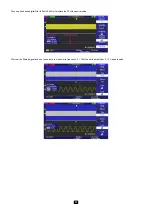
a) Display the signal (possible using the “Autoset” key), then set the parameters as indicated below.
It can be seen that the display is not stable.
Set the triggering to pulse width < 20 ns and adjust the triggering level to close to the low level of the pulse in order to trigger on the fault.
Use the Delayed and LongMem mode in order to be able to analyse the fault and the digital frame in detail.


