background image

22

15. DISTORTION

Demo:                                           with:

 DOX2025

 DOX2040

 DOX2100

 DOX2xxxB

Test Signal

n°15 : Distortion

Nature

1 pseudo-sinusoidal signal containing harmonic distortion

Specs

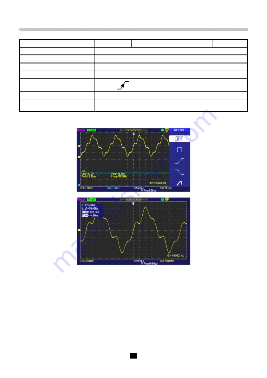
Frequency of the signal ≈ 50 Hz, Vpp ≈ 3.2 V

Oscilloscope Settings

2.5 ms/div. - MAIN = 500 mV/div. DC coupling imperative

Trigger

DC coupling on MAIN, level 50 % of Vpp, for example

Modes

«Oscilloscope» mode

Objective

Display of a frequency-modulated 50 Hz sine wave with components

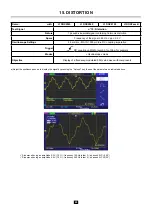
a) Adjust the oscilloscope so as to display the signal by pressing the “Autoset” key, then set the parameters as indicated above.


 Sine wave having an amplitude 0.3 V (10 %) ; frequency 150 Hz (order 3) ; phase shift: PI (180°)


 Sine wave having an amplitude 0.6 V (18 %) ; frequency 250 Hz (order 5) ; phase shift: PI/2 (90°)


Summary of Contents for metrix GX1025

Page 1: ...EN User s manual Signal generator circuit HX0074 demo kit for DOX2xxx and DOX2xxxB Demonstration GX1025 with DOX2xxx and DOX2xxxB...

Page 2: ...GENERATOR TO DEMONSTRATE THE ADVANTAGES OF THE LONGMEM MEMORY DEPTH AND OF THE DIGITAL FILTERS 23 1 1 Influence of memory depth LongMem or Normal on the sampling interval 23 2 USING THE DIGITAL FILTE...

Page 3: ...tor to generate the signals specific to demonstrating the advantages of LongMem long recording memory depths and of using digital filters to observe composite signals PRESENTATION OF THE HX0074 The HX...

Page 4: ...the different display modes Normal Delayed XY a Adjust the oscilloscope so as to display the signals correctly possible using the Autoset key When Autoset is exited the oscilloscope adjusts the vertic...

Page 5: ...ase measurements manual automatic Present the FFT Mathematical function a Adjust the oscilloscope so as to display the signals correctly possible using the Autoset key and select automatic phase measu...

Page 6: ...displays the CH1 signal and its FFT simultaneous The Time cursors can be used to determine the frequencies of the fundamental and of the harmonics The Voltage cursors can be used to determine the amp...

Page 7: ...of the train as soon as the oscilloscope is ready to acquire This is accompanied by a feeling of horizontal instability making the display unusable The proper setting of the Hold Off parameter in the...

Page 8: ...with this type of signal Autoset operation may be aleatory b We are now going to demonstrate the utility of the pulse width triggers The example chosen will serve to synchronize to the chip select si...

Page 9: ...9 Expansion by 25 Expansion by 100 Horizontal displacement of the Zoomed zone by acting on the Position encoder...

Page 10: ...clock This communication setup is found in particular with the protocols of serial links such as the I2C bus USB bus CAN bus Ethernet communication etc The first utility of the operating mode is to de...

Page 11: ...ory Depth Normal The representation is wrong the train of 6 pulses is represented by a single pulse the horizontal resolution is insufficient This is because the sampling rate in Normal Memory Depth i...

Page 12: ...ment we can observe the global shape of the signal and a zoomed zone The measured amplitude Vpp of the signal in the zoomed zone is displayed on the right side of the screen By shifting the zoom windo...

Page 13: ...cope Settings 50 ns to 200 s div MAIN 500 mV div Trigger on MAIN 50 of Vpp Modes Triggered mode preferable Objectives Using automatic measurements F P Tr Tm Vpp Vrms etc Activation of a particular mea...

Page 14: ...div MAIN 2 5 or 5 mV div Trigger on MAIN 50 of Vpp Modes nothing at first then 100 kHz low pass filtering Objectives Triggering and display for a noisy signal Using the Digital filters a Adjust the o...

Page 15: ...ecise representation of signals Delayed and LongMem mode a Adjust the oscilloscope so as to display the pulse trains and a zoomed train of 6 pulses Attention with this type of signal Autoset operation...

Page 16: ...50 mV Modes Select Repetitive Signal Horiz menu Objectives Using triggering on pulse width Using the LongMem and Delayed mode a Display the signal possible using the Autoset key then set the parameter...

Page 17: ...al approximately possible using the Autoset mode then set the parameters as indicated opposite b The signal displayed represents a digital clock at 100 ns By paying attention it may be possible to spo...

Page 18: ...esentation of the Scan mode for the 50 ms div time base Attention the Scan and LongMem modes along with the Scan and Delayed modes are not compatible Attention in Scan mode for the Level to be active...

Page 19: ...19 By placing the triggering level above the mean level of the signal and acting on the width of the positive pulse it is possible to synchronise to the high pulse...

Page 20: ...gger None at first then EXT thresholds on MAIN levels 1 V and 2 6 V Modes Source Level triggering Objective Entry of slow signals Normal trigger mode a Entry of signal no 13 by Front type triggering s...

Page 21: ...lloscope Settings 5 ms div MAIN and AUX 1 V div DC coupling Trigger DC coupling on MAIN 50 of Vpp for example Modes Oscilloscope mode y t Objective Display of a square and a triangular signal a Adjust...

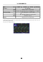
Page 22: ...imperative Trigger DC coupling on MAIN level 50 of Vpp for example Modes Oscilloscope mode Objective Display of a frequency modulated 50 Hz sine wave with components a Adjust the oscilloscope so as t...

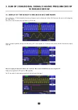
Page 23: ...al having a frequency of 10 MHz in DOTs display mode and Vectors with a main time base of M 250 s div and a Delayed time base of W 25 ns div there is a ratio of 10 000 between the M and W time bases W...

Page 24: ...al memory depth this does not after the cut off frequencies of the filters which depend on the main time base range M 250 s b A low pass digital filter having a high cut off frequency of 25 kHz is app...

Page 25: ...The 2 kHz square wave which is not in the pass band is blocked by the filter leaving only the 60 kHz sinusoidal signal which is in the pass band e A band stop digital filter 25 kHz to 800 kHz is appli...

Page 26: ...el close to zero We use the cursors to measure the high frequency 76 92 kHz When a low pass digital filter having a cut off frequency of 37 5 kHz is applied the 10 kHz sine wave passes but the 80 kHz...

Page 27: ...7 FFT of the signal with the low pass digital filter having a cut off frequency of 37 5 kHz The FFT shows the 10 kHz fundamental but the 80 kHz harmonic has been highly attenuated by the digital filte...

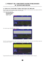
Page 28: ...level is adjusted on the peaks of the product signal Configuration of the oscilloscope Time base range M 100 s Memory Depth Normal Acquisition Samples Display Vectors Then the low frequency of the pro...

Page 29: ...is used to isolate the 700 kHz spectral component Display of the 700 kHz spectral component with delayed time base b A bandpass filter 825 kHz 1 MHz is used to isolated the 900 kHz component Display o...

Page 30: ...s 40 0 kHz because the triggering level is adjusted on the peaks of the product signal Configuration of the oscilloscope Time base range M 1 0 ms Memory Depth Normal Acquisition Samples Display Vector...

Page 31: ...We use a bandpass digital filter 60 kHz 80 kHz to isolate the 70 kHz spectral spike We view the filtered signal and use the cursors to measure its frequency F 70 kHz and its amplitude 5 12 V peak to p...

Page 32: ...32 We separate the 90 kHz spectral spike with a bandpass filter 85 kHz 100 kHz We view the filtered signal and use the cursors to measure its frequency F 90 kHz and its amplitude 5 12 V peak to peak...

Page 33: ...X04128C02 Ed 1 03 2021 Chauvin Arnoux All rights reserved and reproduction prohibited...

Reviews: