24
2. USING THE DIGITAL FILTERS
2.1. 2 KHZ SQUARE WAVE WITH A 62 KHZ SINE WAVE SUPERPOSED ON ITS PLATEAUS
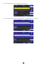
a) Display of the 2 kHz square wave with a 62 kHz sine wave superposed on its plateaus:
Remark: the frequencies of the Digital Filters depend on the sampling frequency and therefore on the time base range (M = 250 µs),
so we recommend observing the details of the signals with the “Delayed” time base (W = 25 µs) and a normal memory depth; this does not after
the cut-off frequencies of the filters, which depend on the main time base range, M = 250 µs.
b) A “low-pass” digital filter having a high cut-off frequency of 25 kHz is applied to this signal:
The 62 kHz sinusoidal signal, which is above the high cut-off frequency of the filter, disappears and the edges of the 2 kHz square wave are
rounded (see below):
c) A “high-pass” digital filter having a low cut-off frequency of 25 kHz is applied:
The 2 kHz square wave is blocked by the high-pass filter leaving only the 60 kHz sinusoidal signal, which is above the low cut-off frequency of the filter.


